Switches, Test points, Lcd adjustment (densitron) – Gasboy 1000 Series FMS Diagnostic Manual User Manual
Page 34
Head Assembly
03/07/03
2-15
Switches
SW1 - Reset Switch
The reset switch starts a hardware and software
reset of the MPU PCB.
SW2 - Pulse Rate Change
The pulse rate change switch is used
during the configuration of system
parameters. It is located on the back
side of the MPU PCB and accessed
through a hole in the sheet metal
mounting bracket. With the switch enabled, the pulse rate for each hose outlet can be changed in
the configuration mode of the system. When the switch is set to enabled, no transactions can
occur at the system and the message REMOTE CONFIGURATION appears on the display.
Upon completion of the configuration, the switch should be set to the disabled position. The
switch can be sealed with a Weights and Measures paper seal when required.
SW3 - Diagnostic Mode
This switch is used to enter and exit the diagnostic
test mode available in the system. See the Diagnostic
Kit and Tests section for specific instructions.
SW4 - DIP Switches
The DIP switches are not used by the Series 1000
and must be left in the OPEN position.
Test Points
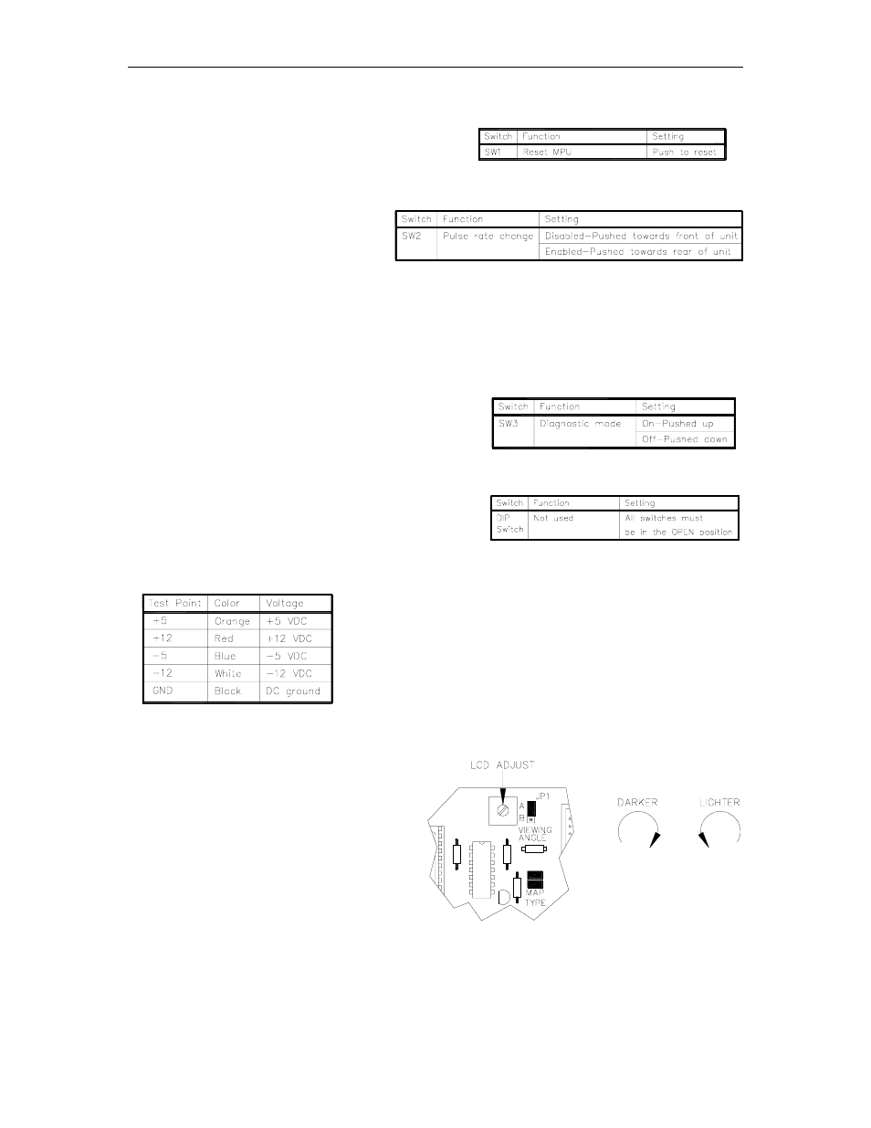
LCD Adjustment (Densitron)
The LCD adjustment potentiometer found at
the top of the MPU PCB controls the
viewing angle (darkness) of the Densitron
LCD display. Turn the control clockwise to
make the display darker and counter-
clockwise to make it lighter. See the LCD
Display section for adjustment of the Okaya
display viewing angle.