4 safety function sto with safety card, 5 reaction time, 4function description – Pilz PMCprotego D.72/000/0/0/2/208-480VAC User Manual
Page 55: 3 control element
Pilz GmbH & Co. KG, Felix-Wankel-Straße 2, 73760 Ostfildern, Germany
Telephone: +49 711 3409-0, Telefax: +49 711 3409-133, E-Mail: [email protected]
4-21
4.3
Control element
4
Function Description
STO2-STATUS: Digital output, switch status STO2
t
d
: Delay time between 1/0 pulse edge of STO1-ENABLE/STO2-ENA-
BLE and 1/0 pulse edge of output STO1-STATUS/ STO2-STATUS
4.3.3.4
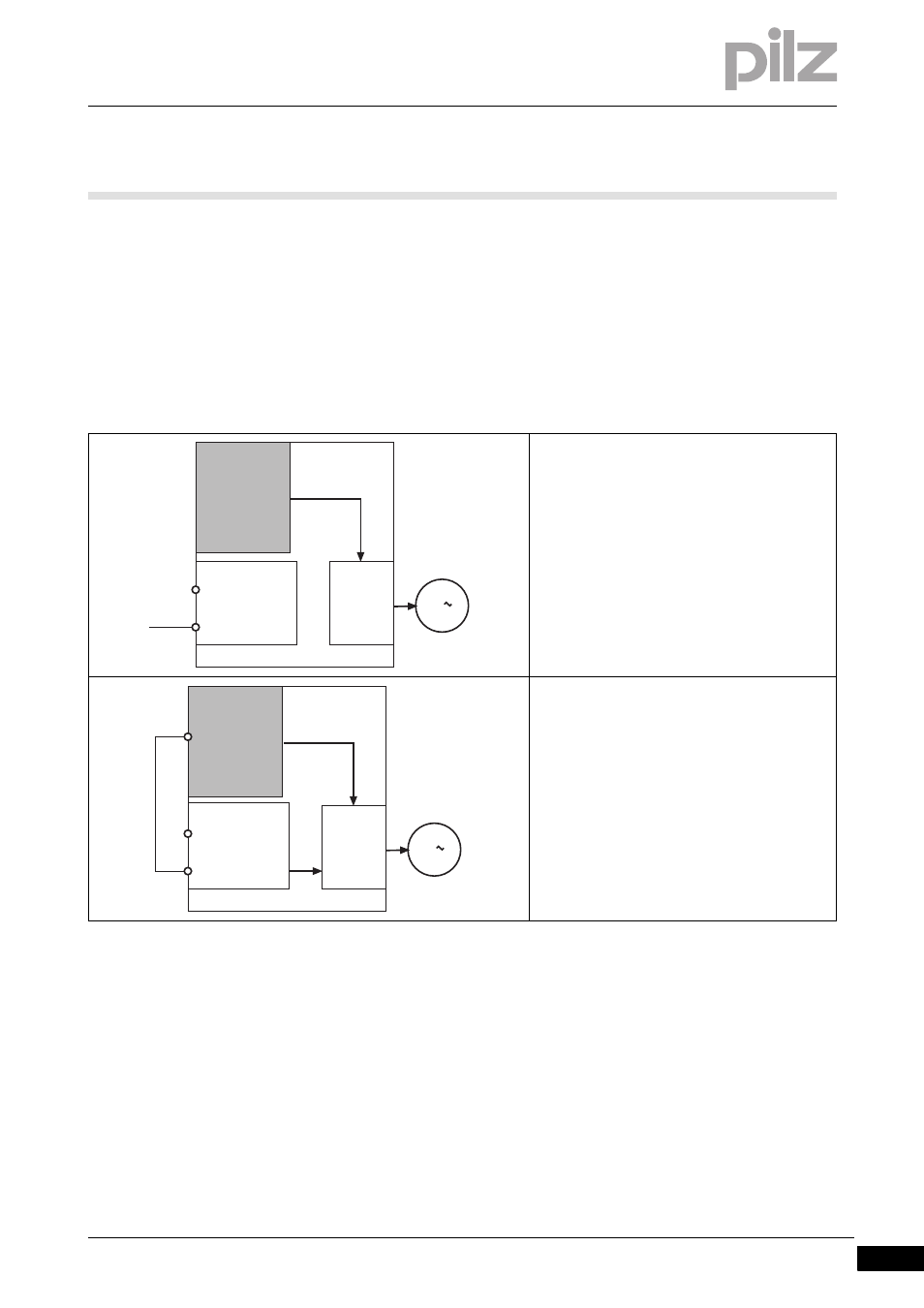
Safety function STO with safety card
Safety function STO with safety card
4-
][Funktion_STO_mit_Sicherheitskarte_D48
With a safety card inserted, activation of the safety function STO can be
single or dual-channel.
4.3.3.5
Reaction time
Reaction time
4-
][Funktion_STO_Reaktionszeit_D48_72
The reaction time of the safety function STO, from the falling edge at the
inputs STO1-ENABLE and STO2-ENABLE to the removal of power to
the motor, is
5 ms on the shutdown route STO1
5 ms on the shutdown route STO2
STO single-channel with safety card
PMCprotego S2 (or when the 2nd shutdown
route is not used on the safety card
PMCprotego S1)
Safety function is activated internally via the
safety card's STO function.
The input STO1-ENABLE has no function.
The input STO2-ENABLE must be connected to
24 VDC.
STO dual-channel with safety card
PMCprotego S1
Safety function is activated internally via the
safety card's STO function
and
output STO SIL3 on the safety card is connect-
ed to STO2-ENABLE as a 2nd shutdown route.
The input STO1-ENABLE has no function.
X4
STO1-ENABLE
STO2-ENABLE
7
5
PMCprotego D.x
PMCpr
otego S2
24 V
POWER
3
STO
X4
STO1-ENABLE
STO2-ENABLE
7
5
PMCprotego D.x
PMCpr
otego S1
X30
19
STO SIL3
STO
STO
POWER
3