6wiring, 7 control element – Pilz PMCprotego D.72/000/0/0/2/208-480VAC User Manual
Page 131
Pilz GmbH & Co. KG, Felix-Wankel-Straße 2, 73760 Ostfildern, Germany
Telephone: +49 711 3409-0, Telefax: +49 711 3409-133, E-Mail: [email protected]
6-23
6.7
Control element
6
Wiring
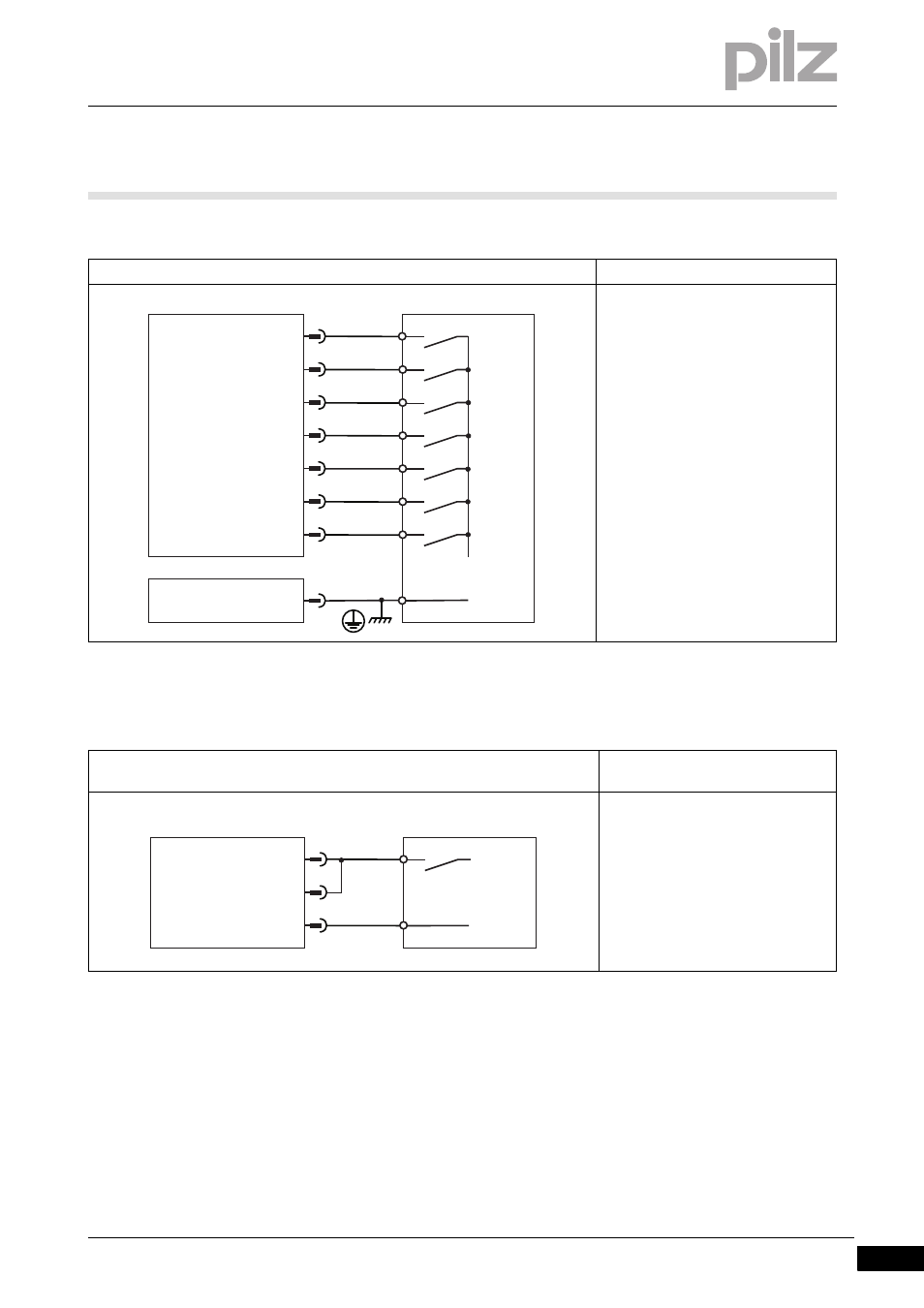
PMCprotego D without a safety card
Connection
Input circuit
Digital input
24 VDC
Referenced to earth: Always connect
DGND (X3B/16) to I/O-GND on the
control system
PSTOP, NSTOP: Evaluation of limit
switch
Pin 6 and 7 is configured as a digital
input in the commissioning software
Input circuit
Digital input: STO1-ENABLE/STO2-
ENABLE
Single-channel
24 VDC
Referenced to earth: Always con-
nect XGND (X4B/3 or 4) to I/O-GND
on the control system
Connect a safe semiconductor out-
put or positive-guided relay contact
NSTOP
1
ENABLE
DIGITAL-IN1
2
3
4
DGND
5
PMCprotego
24 V
I/O-GND
X3A
DIGITAL-INOUT1
DIGITAL-IN4
DIGITAL-IN3
DIGITAL-IN2
DIGITAL-INOUT2
6
7
X3B
16
ENABLE
PSTOP
5
IO-GND
XGND
7
PMCprotego D
X4
STO1-ENABLE
4
STO2-ENABLE
24 V