4 brake resistor, 4function description, 2 power element – Pilz PMCprotego D.72/000/0/0/2/208-480VAC User Manual
Page 43
Pilz GmbH & Co. KG, Felix-Wankel-Straße 2, 73760 Ostfildern, Germany
Telephone: +49 711 3409-0, Telefax: +49 711 3409-133, E-Mail: [email protected]
4-9
4.2
Power element
4
Function Description
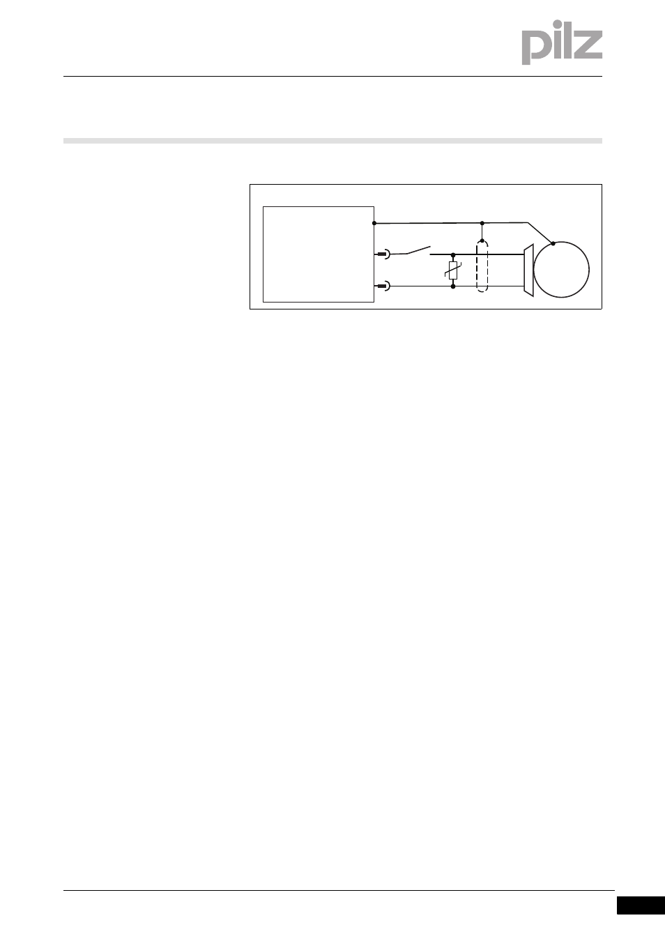
Wiring suggestion:
Fig. 4-5:
Safe motor holding brake
R1: Suppression device
S1: N/O contact from a safety relay
4.2.4
Brake resistor
Brake resistor
4-
][Funktion_Bremswiderstand_protego_D_48_72
When the servo motor is braked, energy is fed back to the servo ampli-
fier. This means that the capacitors in the intermediate circuit are
charged at higher voltages. The servo amplifier switches the brake resis-
tor to the intermediate circuit via the brake chopper. The brake resistor
converts the braking energy into heat.
The servo amplifier PMCprotego D has no integrated brake resistors.
External brake resistors may be connected.
][Funktion_Bremswiderstand_protego_D
Parameter setting
The thresholds for connecting the brake resistor to the mains voltage of
the servo amplifier are adjusted in the commissioning software.
Our Customer Support team can help you calculate the brake power you
will need for your plant.
Single-axis or multi-axis systems
Single amplifier
– If the power regenerated from the motor is greater than the set
brake power (as an average over time or as a peak value), a mes-
sage will appear (see section entitled “Messages/Errors”).
– The servo amplifier detects overvoltage on the intermediate circuit.
The power element shuts down. The following error message ap-
pears: “ F02: Overvoltage”.
– The relay contact for operational readiness, BTB/RTO, opens.
S1
1
2
PMCprotego
X9
BR-
BR+
M
R1