5 encoder systems, 1 resolver, 6wiring – Pilz PMCprotego D.72/000/0/0/2/208-480VAC User Manual
Page 135: 7 control element
Pilz GmbH & Co. KG, Felix-Wankel-Straße 2, 73760 Ostfildern, Germany
Telephone: +49 711 3409-0, Telefax: +49 711 3409-133, E-Mail: [email protected]
6-27
6.7
Control element
6
Wiring
6.7.5
Encoder systems
Encoder systems
6-
6.7.5.1
Resolver
Resolver
6-
][Verdr_Leiterquerschnitte_Verweis
Under “Connection cables”, please note the requirements for the:
Cable cross sections
Insulation material
][Verdr_Geber_Resolver_protego_D
If the cable length > 100 m, speak to our Customer Support.
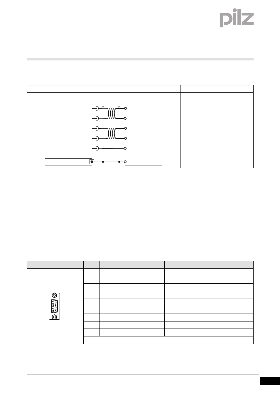
Connection
Input circuit
Analogue input
- Signal range –10 ... +10 V
- Referenced to earth: Always con-
nect AGND (X3B/13) to CNC-GND
on the control system
- Twisted pair, shielded
- Shield connection on the front plate
Connector pin assignment
Connector X2
Pin
Designation
Description
1
Shield
Internal shield
2
ϑ
Thermal switch
3
S4 (Sin2)
Sine input
4
S1 (Cos2)
Cosine input
5
R1 (Ref1)
Reference output
6
ϑ
Thermal switch
7
S2 (Sin1)
Sine input
8
S3 (Cos1)
Cosine input
9
R2 (Ref2)
Reference output
+O1
9
ANALOG-IN1-
10
11
12
AGND
13
PMCprotego
-O1
+/- 10 V
+O2
-O2
+/- 10 V
CNC-GND
GND
X3B
Shield
ANALOG-IN1+
ANALOG-IN2-
ANALOG-IN2+
1
5
6
9