4function description, 2 power element – Pilz PMCprotego D.72/000/0/0/2/208-480VAC User Manual
Page 42
4.2
Power element
4
Function Description
Pilz GmbH & Co. KG, Felix-Wankel-Straße 2, 73760 Ostfildern, Germany
Telephone: +49 711 3409-0, Telefax: +49 711 3409-133, E-Mail: [email protected]
4-8
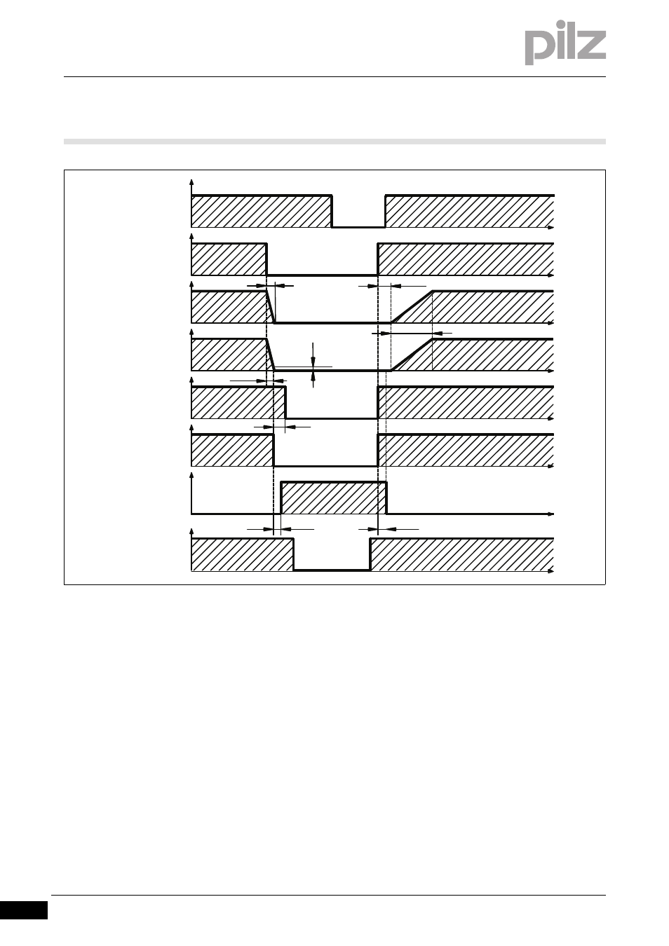
Fig. 4-4:
Timing diagram for motor holding brake
The speed setpoint is brought from 100 ms to 0 within the internal de-
lay time (internal ENABLE). The emergency braking ramp DECDIS is
selectable.
The brake output BR+ switches at a speed of 5 rpm or after 5 s at the
latest (EMRGTO).
The rise times (t
brH
) and fall times (t
brL
) of the motor holding brake de-
pend on the motor type (see motor documentation).
Safe actuation of the motor holding brake
Safe actuation of the holding brake also requires:
The N/O contact from a safety relay within the braking circuit
A suppression device (e.g. varistor or flywheel diode).
][Funktion_Motorhaltebremse_protego_D_48_72_Schaltung
ANALOG-IN1
ENABLE
n-set value
internal
Brake BR+
Motor speed
Internal
enable
Braking power
STO-ENABLE
Emergency braking ramp
TBRAKE0 def. 20 ms
Rampe+
TBRAKE def. 100 ms
EMRGTO
max. 5 s
VEL0
DECDIS
tbrH
tbrL
5
t
t
t
t
t
t
t
t
U
U
U
U
U
U
n
F