Ethernet link integrity support, Figure 23-2, Figure 23-3 – Cisco 15327 User Manual
Page 385
23-5
Ethernet Card Software Feature and Configuration Guide, R7.2
Chapter 23 E-Series and G-Series Ethernet Operation
Ethernet Link Integrity Support
Figure 23-2
G-Series Gigabit EtherChannel (GEC) Support
Although the G-Series cards do not actively run GEC, they support the end-to-end GEC functionality of
attached Ethernet devices. If two Ethernet devices running GEC connect through G-Series cards to an
ONS network, the ONS SONET/SDH side network is transparent to the EtherChannel devices. The
EtherChannel devices operate as if they are directly connected to each other. Any combination of
G-Series parallel circuit sizes can be used to support GEC throughput.
GEC provides line-level active redundancy and protection (1:1) for attached Ethernet equipment. It can
also bundle parallel G-Series data links together to provide more aggregated bandwidth. Spanning Tree
Protocol (STP) operates as if the bundled links are one link and permits GEC to utilize these multiple
parallel paths. Without GEC, STP permits only a single nonblocked path. GEC can also provide G-Series
card-level protection or redundancy because it can support a group of ports on different cards (or
different nodes) so that if one port or card has a failure, traffic is rerouted over the other port or card.
The end-to-end Ethernet link integrity feature can be used in combination with Gigabit EtherChannel
(GEC) capability on attached devices. The combination provides an Ethernet traffic restoration scheme
that has a faster response time than alternate techniques such as spanning tree rerouting, yet is more
bandwidth efficient because spare bandwidth does not need to be reserved.
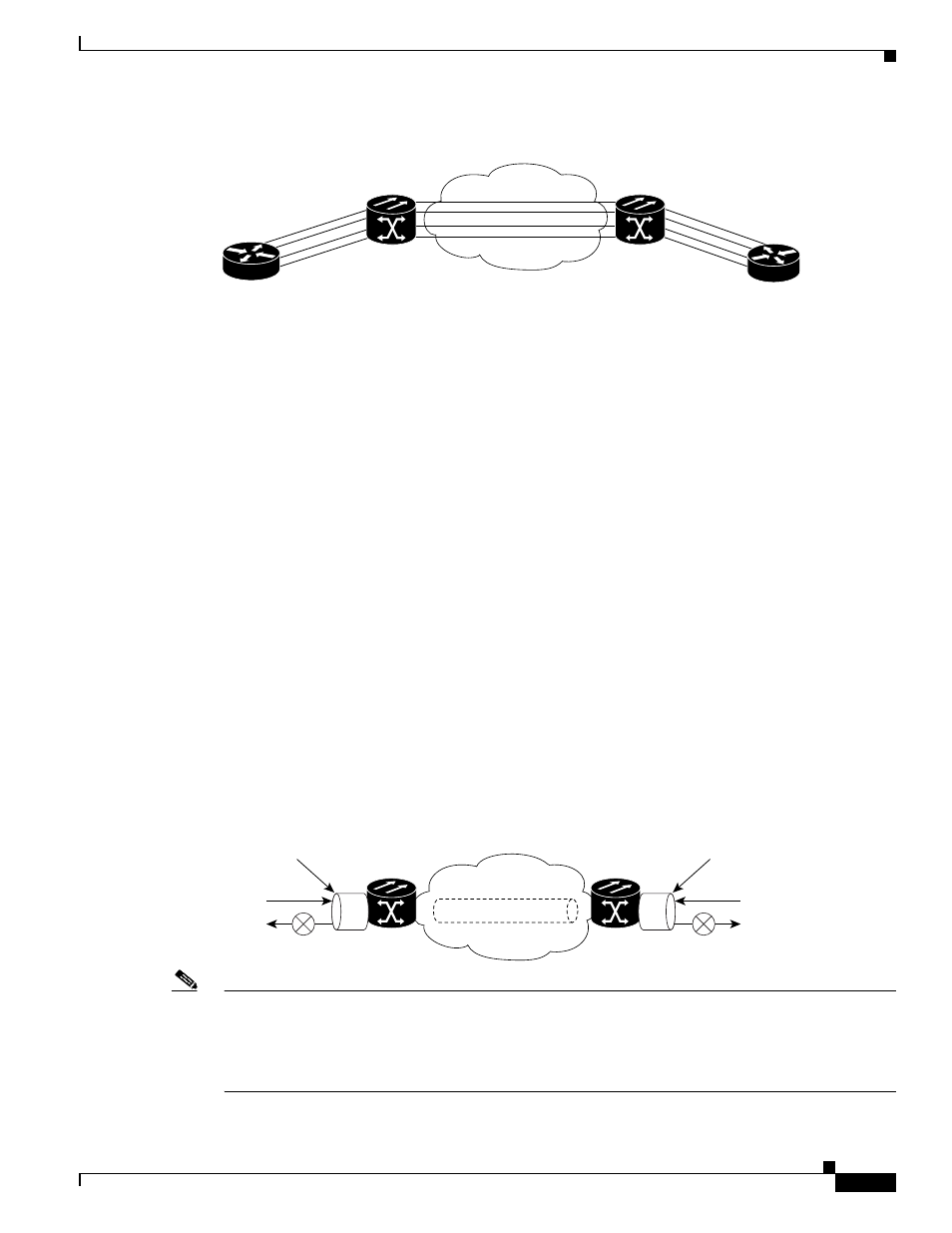
Ethernet Link Integrity Support
The G-Series supports end-to-end Ethernet link integrity (
). This capability is integral to
providing an Ethernet private line service and correct operation of Layer 2 and Layer 3 protocols on the
attached Ethernet devices. End-to-end Ethernet link integrity essentially means that if any part of the
end-to-end path fails, the entire path fails. Failure of the entire path is ensured by turning off the transmit
lasers at each end of the path. The attached Ethernet devices recognize the disabled transmit laser as a
loss of carrier and consequently an inactive link.
Figure 23-3
End-to-End Ethernet Link Integrity Support
Note
Some network devices can be configured to ignore a loss of carrier condition. If a device configured to
ignore a loss of carrier condition attaches to a G-Series card at one end, alternative techniques (such as
use of Layer 2 or Layer 3 keep-alive messages) are required to route traffic around failures. The response
time of such alternate techniques is typically much longer than techniques that use link state as
indications of an error condition.
67833
SONET/SDH Circuits
Gigabit EtherChannel
Gigabit EtherChannel
ONS Node
ONS Node
ONS Node
G-Series port
67952
Tx
Rx
ONS Node
G-Series port
Tx
Rx
STS-N/VC-N
SONET/SDH