E-series circuit protection, E-series point-to-point ethernet circuits, Figure 23-19 – Cisco 15327 User Manual
Page 404: Table 23-6
23-24
Ethernet Card Software Feature and Configuration Guide, R7.2
Chapter 23 E-Series and G-Series Ethernet Operation
E-Series Circuit Protection
E-Series Circuit Protection
Different combinations of E-Series circuit configurations and SONET/SDH network topologies offer
different levels of E-Series circuit protection.
details the available protection.
Note
Before making Ethernet connections, choose an STS/STM circuit size.
Note
To make an STS-12c/VC4-4c Ethernet circuit, Ethernet cards must be configured in single-card
EtherSwitch or port-mapped mode. Multicard mode does not support STS-12c/VC4-4c Ethernet circuits.
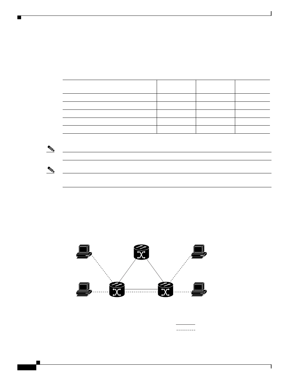
E-Series Point-to-Point Ethernet Circuits
The ONS nodes can set up a point-to-point (straight) Ethernet circuit as single-card, port-mapped, or
multicard circuit (
).
Figure 23-19
Multicard EtherSwitch Point-to-Point Circuit
Single-card EtherSwitch and port-mapped modes provide a full STS-12c of bandwidth between two
Ethernet circuit endpoints (
).
Table 23-6
Protection for E-Series Circuit Configurations
Configuration
Path Protection
(SNCP)
BLSR
(MS-SPRing)
1 + 1
Point-to-point multicard EtherSwitch
None
SONET/SDH
SONET/SDH
Point-to-point single-card EtherSwitch
SONET/SDH
SONET/SDH
SONET/SDH
Point-to-point port-mapped mode
SONET/SDH
SONET/SDH
SONET/SDH
Shared packet ring multicard EtherSwitch
STP
SONET/SDH
SONET/SDH
Common control card switch
STP
STP
STP
43272
ONS Node 1
ONS Node 2
192.168.1.100
255.255.255.0
VLAN test 1
Slot 5, Port 1
192.168.1.75
255.255.255.0
VLAN test 1
Slot 17, Port 1
192.168.1.25
255.255.255.0
VLAN test 1
Slot 4, Port 1
192.168.1.50
255.255.255.0
VLAN test 1
Slot 15, Port 1
ONS Node 3
SONET
Ethernet