Ethernet cos, Figure 14-1, Figure 14-2 – Cisco 15327 User Manual
Page 211
14-3
Ethernet Card Software Feature and Configuration Guide, R7.2
Chapter 14 Configuring Quality of Service
Ethernet CoS
Figure 14-1
IP Precedence and DSCP
Ethernet CoS
Ethernet CoS refers to three bits within a four byte IEEE 802.1Q (VLAN) header used to indicate the
priority of the Ethernet frame as it passes through a switched network. The CoS bits in the IEEE 802.1Q
header are commonly referred to as the IEEE 802.1p bits. There are three CoS bits that provide eight
classes, matching the number delivered by IP precedence. In many real-world networks, a packet might
traverse both Layer 2 and Layer 3 domains. To maintain QoS across the network, the IP ToS can be
mapped to the Ethernet CoS and vice versa, for example, in linear or one-to-one mapping, because each
mechanism supports eight classes. Similarly, a set of DSCP values (64 classes) can be mapped into each
of the eight individual Ethernet CoS values.
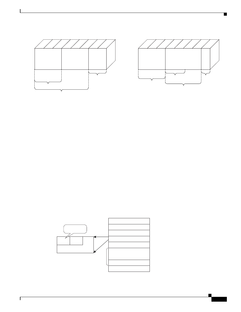
shows an IEEE 802.1Q Ethernet frame, which
consists of a 2-byte Ethertype and a 2-byte tag (IEEE 802.1Q tag) on the Ethernet protocol header.
Figure 14-2
Ethernet Frame and the CoS Bit (IEEE 802.1p)
96499
DS-Field
Class Selector
Codepoints
Currently
Unused
Differentiated Services Code Point
AFC 2474
DSCP
CU
0
Bits
1
2
3
4
5
6
7
RFC 1122
RFC 1349
Must
be
zero
DTR-Bits
Bits (0-2): IP-Precedence Defined
111 (Network Control)
110 (Internetwork Control)
101 (CRITIC/ECP)
100 (Flash Override)
011 (Flash)
101 (Immediate)
001 (Priority)
000 (Routine)
Bits (3-6): Type of Service Defined
0000 (all normal)
1000 (minimize delay)
0100 (maximize throughput)
0010 (maximize reliability)
0001 (minimize monetary cost)
Precedence
Type of Service
MBZ
0
Bits
1
2
3
4
5
6
7
96496
Destination Address
6
Source Address
6
Type=8100
2
Tag Control Information
2
Type/Length
2
MAC DATA
PAD
42~1500
FCS
4
IEEE 802.1Q Tag
VLAN ID
CFI
CoS
IEEE 802.1p
(3 bits)