Vrf lite configuration example, Figure 13-1 – Cisco 15327 User Manual
Page 203
13-3
Ethernet Card Software Feature and Configuration Guide, R7.2
Chapter 13 Configuring VRF Lite
VRF Lite Configuration Example
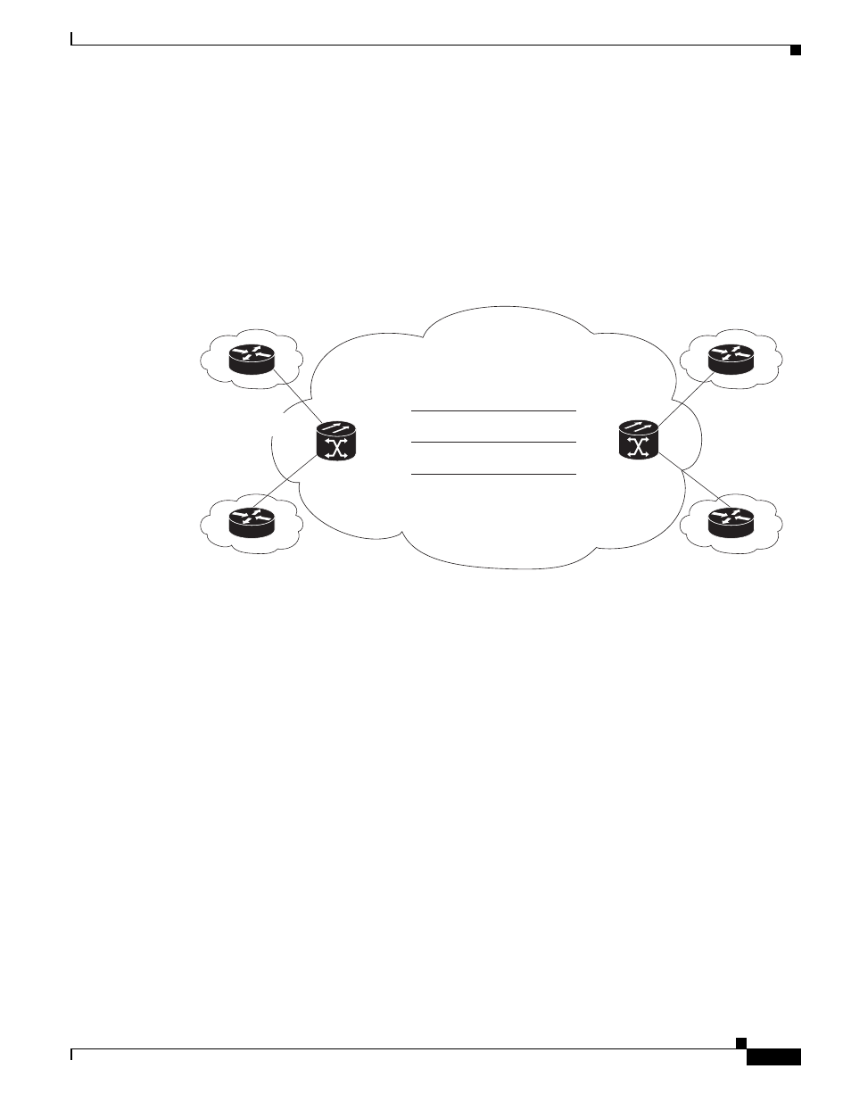
VRF Lite Configuration Example
shows an example of a VRF Lite configuration. The configurations for Router A and Router
and
, respectively. The associated routing
tables are shown in
through
Figure 13-1
VRF Lite—Sample Network Scenario
Example 13-2 Router A Configuration
hostname Router_A
!
ip vrf customer_a
rd 1:1
route-target export 1:1
route-target import 1:1
!
ip vrf customer_b
rd 2:2
route-target export 2:2
route-target import 2:2
!
bridge 1 protocol ieee
bridge 2 protocol ieee
bridge 3 protocol ieee
!
!
interface FastEthernet0
no ip address
!
interface FastEthernet0.1
encapsulation dot1Q 2
ip vrf forwarding customer_a
ip address 192.168.1.1 255.255.255.0
bridge-group 2
83
244
Customer A
Customer B
Customer B
Customer A
ONS 15454
with ML100T-12
Router_A
ONS 15454
with ML100T-12
Router_B
Fast Ethernet 1.1
192.168.2.1
Fast Ethernet 0.1
192.168.1.1.
Fast Ethernet 0.1
192.168.4.1
Fast Ethernet 1.1
192.168.5.1
Service Provider Network
POS 0.1
POS 0.1
192.168.50.2
192.168.50.1
STS-N
POS 0.2
POS 0.2
192.168.100.2
192.168.100.1
STS-N
POS 0.3
POS 0.3
192.168.200.2
192.168.200.1
STS-N