Figure 8-2 – Cisco 15327 User Manual
Page 132
8-4
Ethernet Card Software Feature and Configuration Guide, R7.2
Chapter 8 Configuring VLANs
IEEE 802.1Q VLAN Configuration
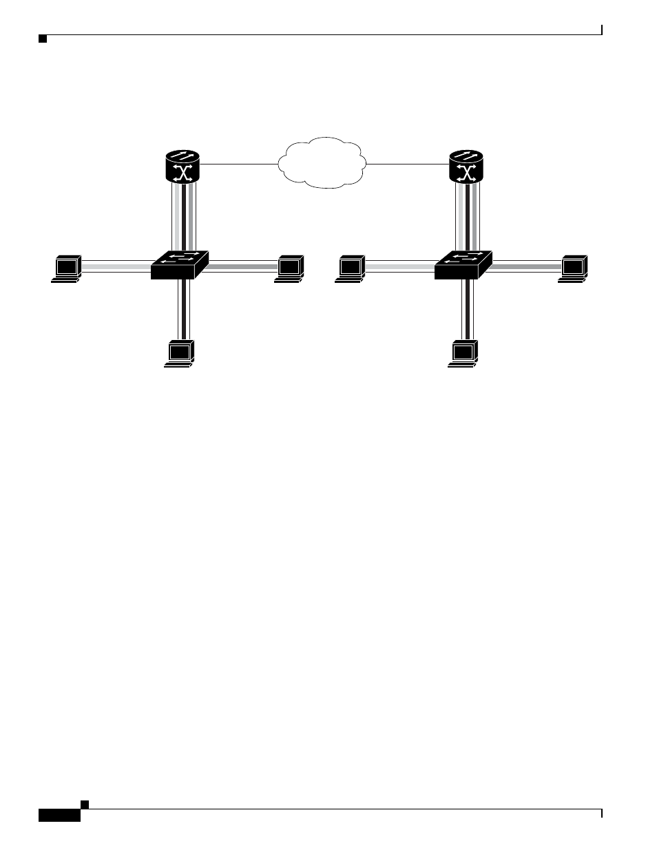
Figure 8-2
Bridging IEEE 802.1Q VLANs
shows how to configure VLANs for IEEE 802.1Q VLAN encapsulation. Use this
configuration for both router A and router B. The example is shown in
:
Example 8-1
Configure VLANs for IEEE 802.1Q VLAN Encapsulation
bridge 1 protocol ieee
bridge 2 protocol ieee
bridge 3 protocol ieee
bridge 4 protocol ieee
!
!
interface FastEthernet0
no ip address
!
interface FastEthernet0.1
encapsulation dot1Q 1 native
bridge-group 1
!
interface FastEthernet0.2
encapsulation dot1Q 2
bridge-group 2
!
interface FastEthernet0.3
encapsulation dot1Q 3
bridge-group 3
!
interface FastEthernet0.4
encapsulation dot1Q 4
bridge-group 4
!
interface POS0
no ip address
crc 32
ONS 15454
with ML100T-12
ONS 15454
with ML100T-12
POS 0
POS 0
Router_A
Router_B
83002
SONET/SDH
Fast Ethernet 0.1
Host station
VLAN 2
Host station
Host station
VLAN 3
VLAN 4
Fast Ethernet 0.3
Fast Ethernet 0.2
Fast Ethernet 0.4
Switch
802.1.Q
Fast Ethernet 0.1
Host station
VLAN 2
Host station
Host station
VLAN 3
VLAN 4
Fast Ethernet 0.3
Fast Ethernet 0.2
Fast Ethernet 0.4
Switch
802.1.Q
Native VLAN 1
Native VLAN 1