E-series shared packet ring ethernet circuits, Figure 23-20, Figure 23-21 – Cisco 15327 User Manual
Page 405
23-25
Ethernet Card Software Feature and Configuration Guide, R7.2
Chapter 23 E-Series and G-Series Ethernet Operation
E-Series Shared Packet Ring Ethernet Circuits
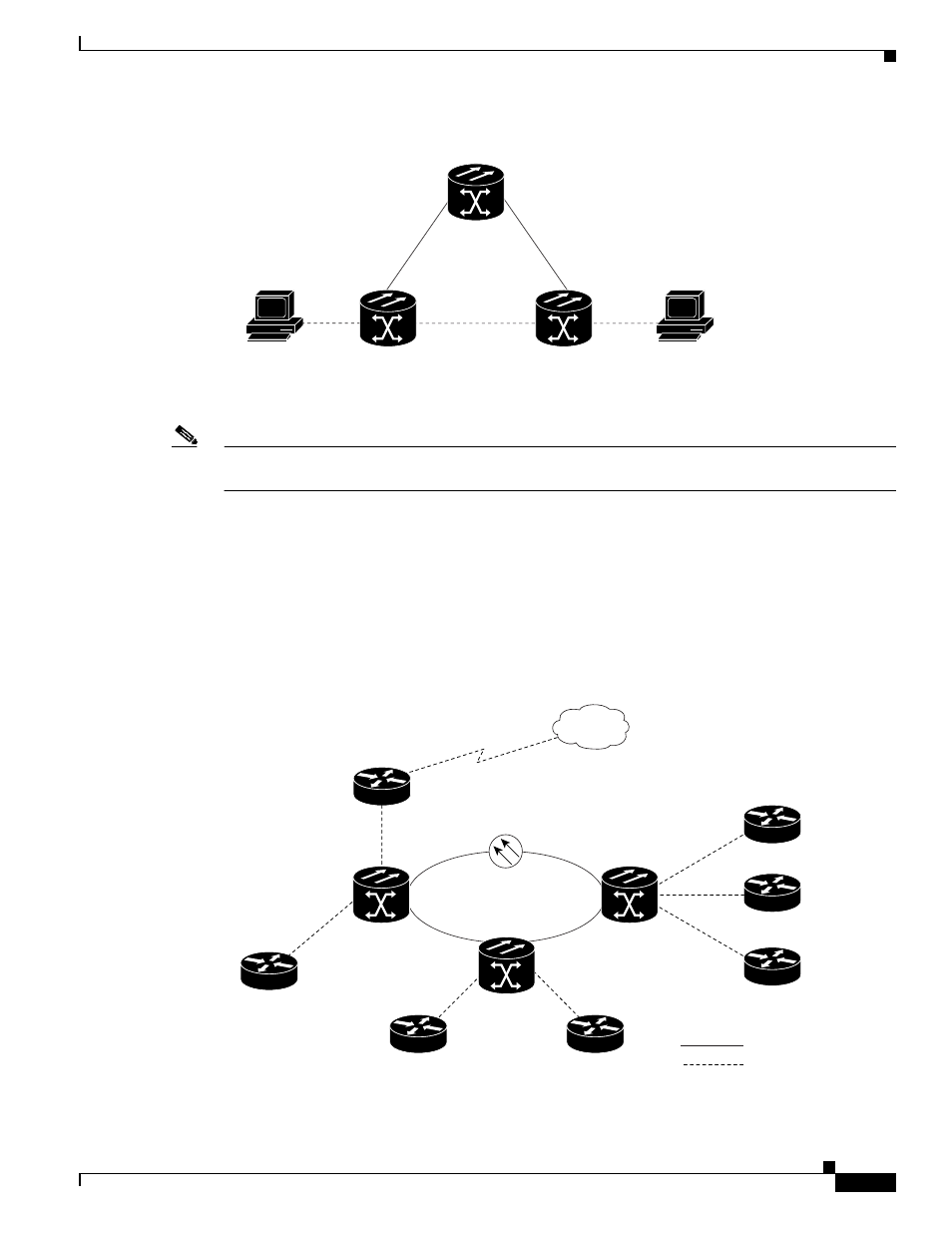
Figure 23-20
Single-Card EtherSwitch or Port-Mapped Point-to-Point Circuit
Note
A port-mapped, point-to-point circuit cannot join an E-Series port-based VLAN, but can transport
external VLANs.
E-Series Shared Packet Ring Ethernet Circuits
A shared packet ring allows additional nodes (besides the source and destination nodes) access to an
Ethernet STS circuit. The E-Series card ports on the additional nodes can share the circuit’s VLAN and
bandwidth.
illustrates a shared packet ring. Your network architecture might differ from
the example.
Figure 23-21
Shared Packet Ring Ethernet Circuit
ONS 15454 3
ONS 15454 2
ONS 15454 1
192.168.1.50
255.255.255.0
VLAN test
Slot 15
192.168.1.25
255.255.255.0
VLAN test
Slot 4
32161
ONS Node
ONS Node
Access router
Backbone router
Access router
Access router
Access router
SONET/SDH Ring
Access router
Access router
ONS Node
32165
SONET
Ethernet