Pos channel configuration example – Cisco 15327 User Manual
Page 153
10-5
Ethernet Card Software Feature and Configuration Guide, R7.2
Chapter 10 Configuring Link Aggregation
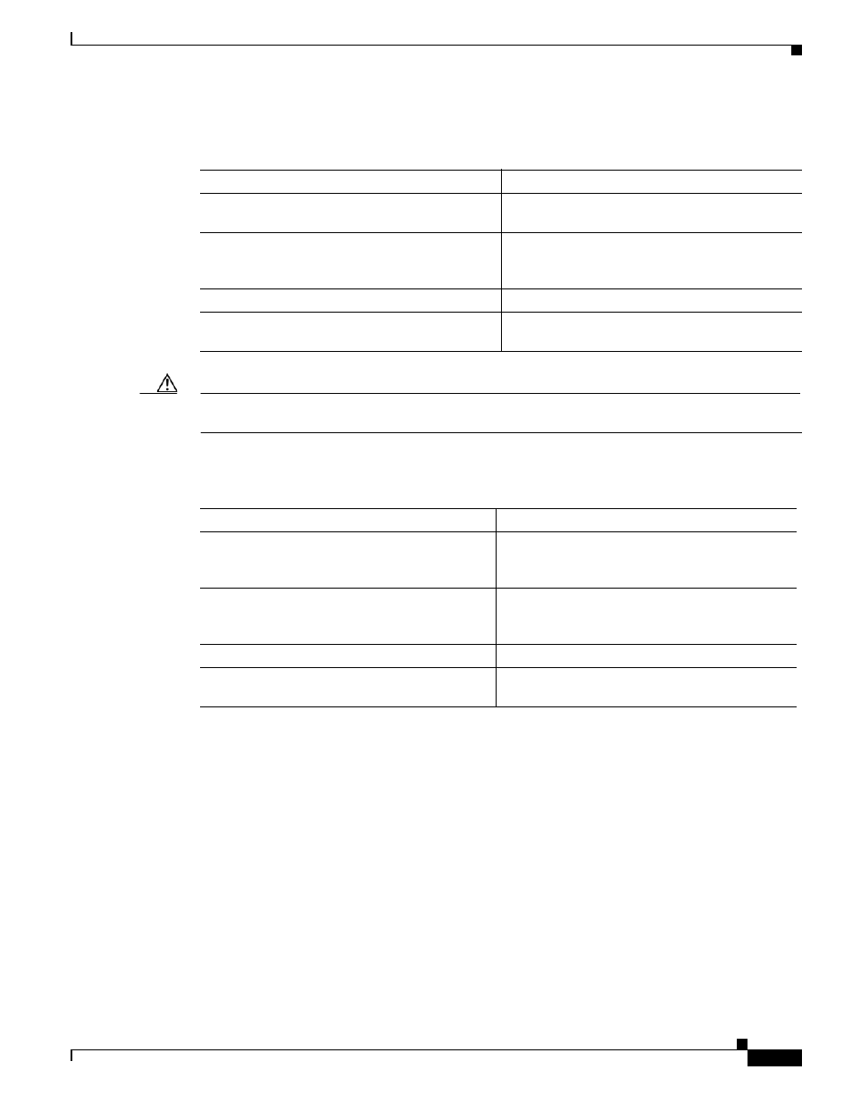
POS Channel Configuration Example
To create a POS channel interface, perform the following procedure, beginning in global configuration
mode:
Caution
The POS channel interface is the routed interface. Do not enable Layer 3 addresses on any physical
interfaces. Do not assign bridge groups on any physical interfaces because doing so creates loops.
To assign POS interfaces to the POS channel, perform the following procedure, beginning in global
configuration mode:
POS Channel Configuration Example
shows an example of POS channel configuration. The associated code is provided in
(Switch A) and
(Switch B).
Command
Purpose
Step 1
Router(config)# interface port-channel
channel-number
Creates the POS channel interface. You can
configure one POS channel on the ML-Series card.
Step 2
Router(config-if)# ip address
ip-address
subnet-mask
Assigns an IP address and subnet mask to the POS
channel interface (required only for the Layer 3
POS channel).
Step 3
Router(config-if)# end
Exits to privileged EXEC mode.
Step 4
Router# copy running-config startup-config
(Optional) Saves configuration changes to
NVRAM.
Command
Purpose
Step 1
Router(config)# interface pos
number
Enters the interface configuration mode to
configure the POS interface that you want to
assign to the POS channel.
Step 2
Router(config-if)# channel-group
channel-number
Assigns the POS interface to the POS channel. The
channel number must be the same channel number
that you assigned to the POS channel interface.
Step 3
Router(config-if)# end
Exits to privileged EXEC mode.
Step 4
Router# copy running-config startup-config
(Optional) Saves the configuration changes to
NVRAM.