TeeJet TASC-6100 User Manual
Page 78
B-6
TASC 6100
98-05018
R2
CE & S
TANDARD
V
ERSION
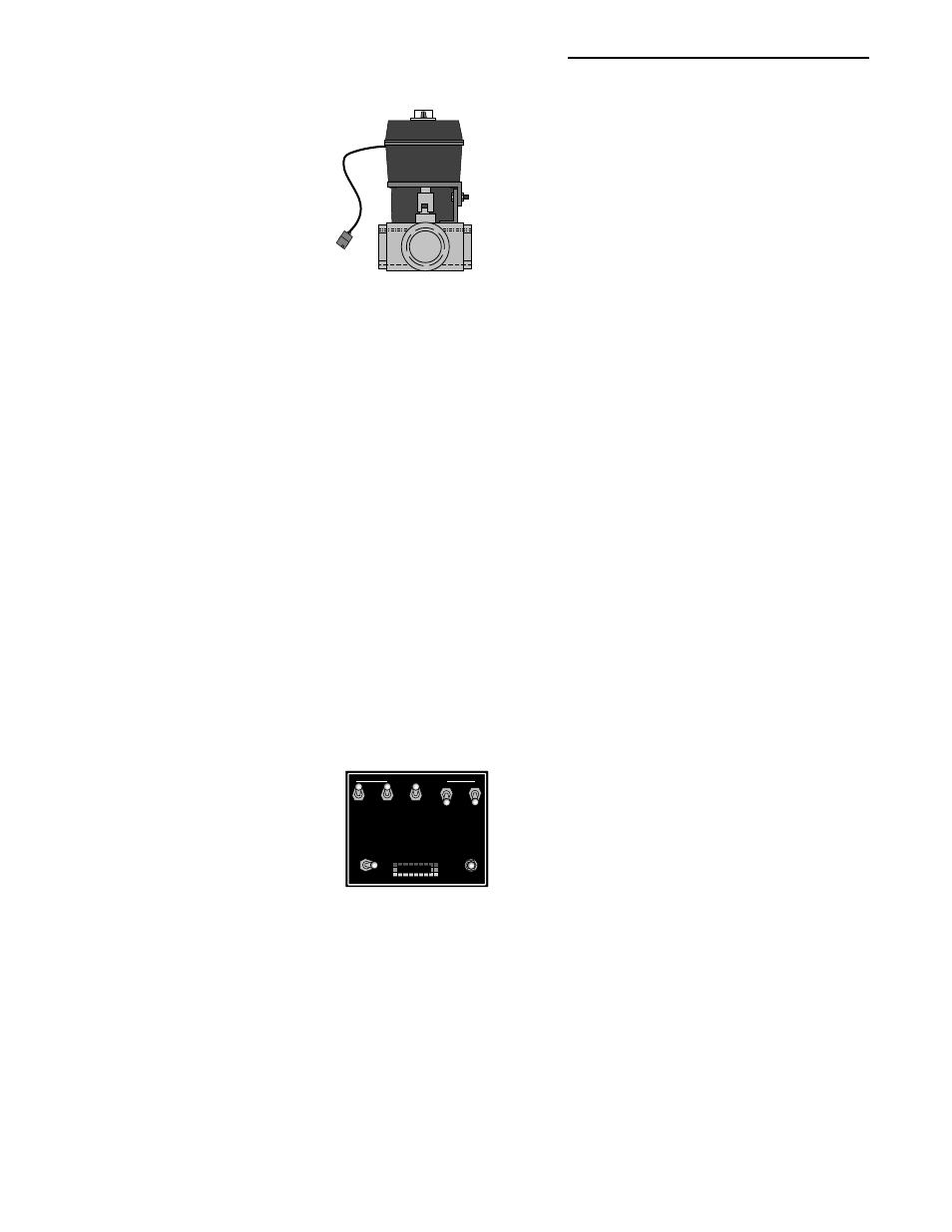
The flow control valve may be a straight through
valve, or a three port Auto-Range
®
type valve (poly or
stainless), controlling the liquid flow directly, or it
may be a hydraulic valve, controlling the speed of a
hydraulic motor driving the liquid pump or granular
conveyor.
Sometimes an applicator is already equipped with an
electronically controlled flow control valve. If the
valve meets the speed and precision requirements of
the TASC 6100 system, it can possibly be adapted for
use. Check with your MID-TECH
®
dealer, or the
factory, about the use of a specific valve.
5. B
OOM
I
NTERFACE
The TASC 6100 control console must know what
boom sections are active at any time, in order to adjust
chemical flow rates appropriately. The console can
monitor the status of as many as nine separate boom
sections. The console can also sense the operation of
an Implement Status switch which would result in a
selectable response by the flow control valve (position
held or full closure). Finally, the system can be
equipped with an optional Ground Speed Override
switch which, when activated, will cause the control
console, under certain conditions, to ignore the actual
ground speed and use a pre-selected "Override Speed”
to control the application rate.
The standard TASC 6100 System is supplied with a
five position boom interface cable which plugs
directly into the rear of the TASC 6100 console and
allows connection of up to five boom control switches
and one status switch. An optional nine boom interface
cable is available for larger applicators.
An optional boom control switch box, such as the one
shown in Fig. B-8, is available to serve those sprayers
not already equipped with boom switches. Boom
switch boxes are offered in three, five, or nine boom
sizes and they are complete with wiring harnesses. The
switch box also provides a Master ON/OFF boom
switch and a Ground Speed Override switch and acts
as an interface for an implement status switch. The
wiring harness from the boom switch box plugs
directly into the back of the TASC 6100 control
Fig. B-7. Flow
Control Valve
BOOM CONTROL SWITCHES
MASTER
ON
OFF
OFF
GSO
AUTO
MIDWEST TECHNOLOGIES, INC.
MID-TECH
®
Fig. B-8. Boom Control
Switchbox