TeeJet TASC-6100 User Manual
Page 7
1-1
98-05018
R2
TASC 6100
Switches& Cont.
CE & S
TANDARD
V
ERSION
%Rate
DISPLAY SELECTOR
Speed
Area
Width
Distance
Fan RPM
Test
Speed
PSI/Prime
Total Applied
Product Vol.
Appl. Rate
OFF
SET- UP
DEC.
ON
OPERATE
INC.
1 2 3
4 5 6 7 8 9
BOOMS
Scan
MID-TECH
MIDWEST TECHNOLOGIES, INC.
TASC-6100
Rate Controller
®
Alt.-Rate
Standard Rate
OFF
1
2
3
4
6
5
-Ac
Flow
Gal./
S
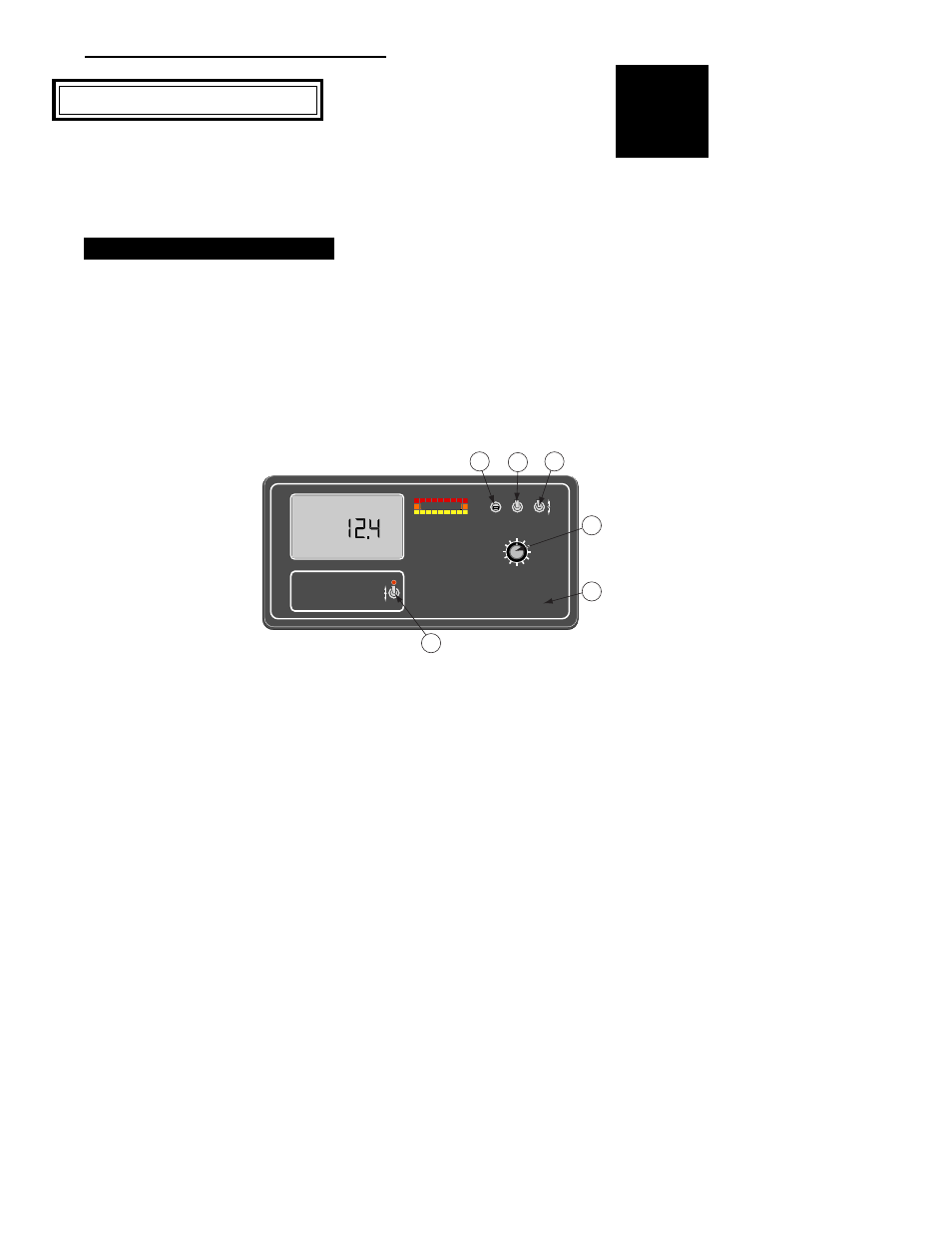
everal switches and indicators serve as the
interface between the operator and the Mid-
Tech control system.
C
ONSOLE
S
WITCHES
AND
I
NDICATORS
T
his section shows the location of each switch
and indicator found on the TASC 6100 control
console and discusses its function in both the
Operate and Setup modes.
P
OWER
S
WITCH
The power switch (see #1 in Fig. 1-1) controls power
to the console. The CE console has an "Auto Power
Down" feature which
powers the console off
after a operator selectable
time has elapsed. The
console has a nonvolatile
memory so it "remembers"
the constants and data
previously entered, even
with the power removed.
NOTE: The “Auto Power Down Feature is only
available on the CE version of the console (CE
designation label on back of console).
M
ODE
S
ELECTOR
S
WITCH
The Mode Selector switch (see #2 in Fig. 1-1)
switches between the OPERATE and SET-UP modes
of the control console. This switch must be in the
“OPERATE” position when applying product. The
“SET-UP” position is used for entering set-up
information into the console. In the SET-UP Mode an
“Err” message appears if a position which can not be
programmed is selected.
C
HAPTER
1 S
WITCHES
AND
C
ONTROLS
Fig. 1-1. TASC
Console Switches and
Indicators