Calculating the initial rate sensor cal – TeeJet TASC-6100 User Manual
Page 37
2-21
98-05018
R2
CE & StandardVersion
TASC 6100
Setup
& Cal.
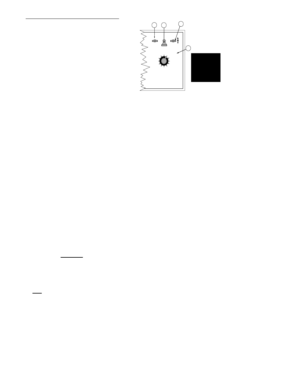
tion of the fan (spinner) must be entered using the
following procedure:
A. Set the console to the following positions;
1. Power
ON
2. Mode Selector
SET- UP
3. Display Selector
Fan RPM
The current Fan Calibration number is displayed.
B. Use the INC./DEC. switch to set this number to the
desired value.
R
ATE
S
ENSOR
C
ALIBRATION
Calculating The Initial Rate Sensor Cal. #
(Spreader Constant)
It is necessary to enter a Spreader Constant in TASC 6100
to ensure an accurate output from the conveyor. The
spreader constant represents the number of sensor pulses
per cubic foot of material discharged. The constant is
different for different gate settings on adjustable spread-
ers. Constants relating to particular gate settings should
be calibrated and recorded for the spreader.
Calculation of the initial spreader constant requires the
following information:
1) Gate height (H) and width (W) in inches
2) Number of sensor pulses for each revolution of the
spreader rate sensor (P)
3) The distance the conveyor moves during one
revolution of the spreader rate sensor (D), in inches.
Calculate the initial spreader constant as follows:
Where: Ft
3
r
is the volume discharged during each
revolution of the spreader rate sensor, in Cubic Feet.
Continue as follows:
DISPLAY SELECTOR
Speed
Area
Impl. Width
Distance
Test
Speed
PSI/Prime
Total Applied
Application Rate
OFF
SET- UP
DEC.
ON
OPERATE
INC.
Scan
Product Vol.
Fan RPM
BOOMS
1 2 3 4 5 6 7 8 9
% Rate
A-2
B
A-3
A-1
D x W x H
1728
= Ft
3
r
P
Ft
3
r
= Initial Calibration Number (Spreader Constant)