TeeJet TASC-6100 User Manual
Page 61
6-1
98-05018
R2
TASC 6100
Emergency
CE & S
TANDARD
V
ERSION
I
f the operator is experiencing a failure of the
ground speed sensor, the main flow control valve,
or the flow or rate sensor, the first step is to
carefully check the wiring harnesses for obvious
problems and follow the suggested troubleshooting
advice outlined in chapter 5.0 of this manual. Assum-
ing there is no success in getting the failed component
to respond, the following procedures are suggested, as
temporary measures, until the component can be
repaired or replaced.
The operator, choosing to use one of the following
procedures, should realize that application accu-
racy is reduced. If this reduced accuracy is accept-
able, these procedures will allow operation to
continue on a temporary basis.
G
ROUND
S
PEED
S
ENSOR
F
AILURE
T
he control console internally generates a speed
signal when operated with the "GROUND
SPEED OVERRIDE" (GSO) function activated.
When the unit is operated in the GSO mode, the
control console establishes the application rate as if the
vehicle were actually moving across the field at the
programmed GSO speed. This feature can be used to
operate the unit, under reduced accuracy, in the event
of a failure of the speed sensor.
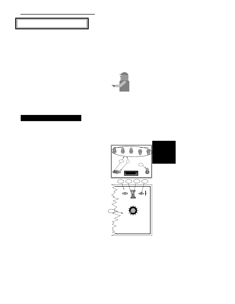
A. Disconnect the speed sensor cable from the back
of the TASC 6100 console.
B. With the vehicle stopped, condition the console
as follows:
1. All Boom switches (or Master switch)OFF
2. Power
ON
3. Mode Selector
SET-UP
4. Display Selector
SPEED
5. Using the INC./DEC. switch, set the GSO
speed for the normal spraying speed, (See
Page 3-5 for additional information).
Mid-T
Mid-T
ech
ech
C
HAPTER
6 E
MERGENCY
O
PERATION
DISPLAY SELECTOR
Speed
Field Area
Impl. Width
Distance
Test
Speed
Prime
Total Applied
Application Rate
OFF
SET- UP
DEC.
ON
OPERATE
INC.
Scan
Product Vol.
Total Area
BOOMS
1 2 3 4 5 6 7 8 9
% Rate
B-2
B-3
B-4
B-5
C-1
BOOM CONTROL SWITCHES
MASTER
ON
OFF
OFF
GSO
AUTO
MIDWEST TECHNOLOGIES, INC.
MID-TECH
¨
B-1
C-3
D