4 mounting kit, 5 purging air switchover, 6 restrictors – Moniteur 50 Series SMART Positioners User Manual
Page 24
Design and Method of Operation
2-6
Positioner SIPART PS2/SIPART PS2 PA
C79000-G7476-C150–01
2.2.4 Mounting kit
The positioner can be mounted on nearly all common types of actua-
tors using the appropriate mounting kit.
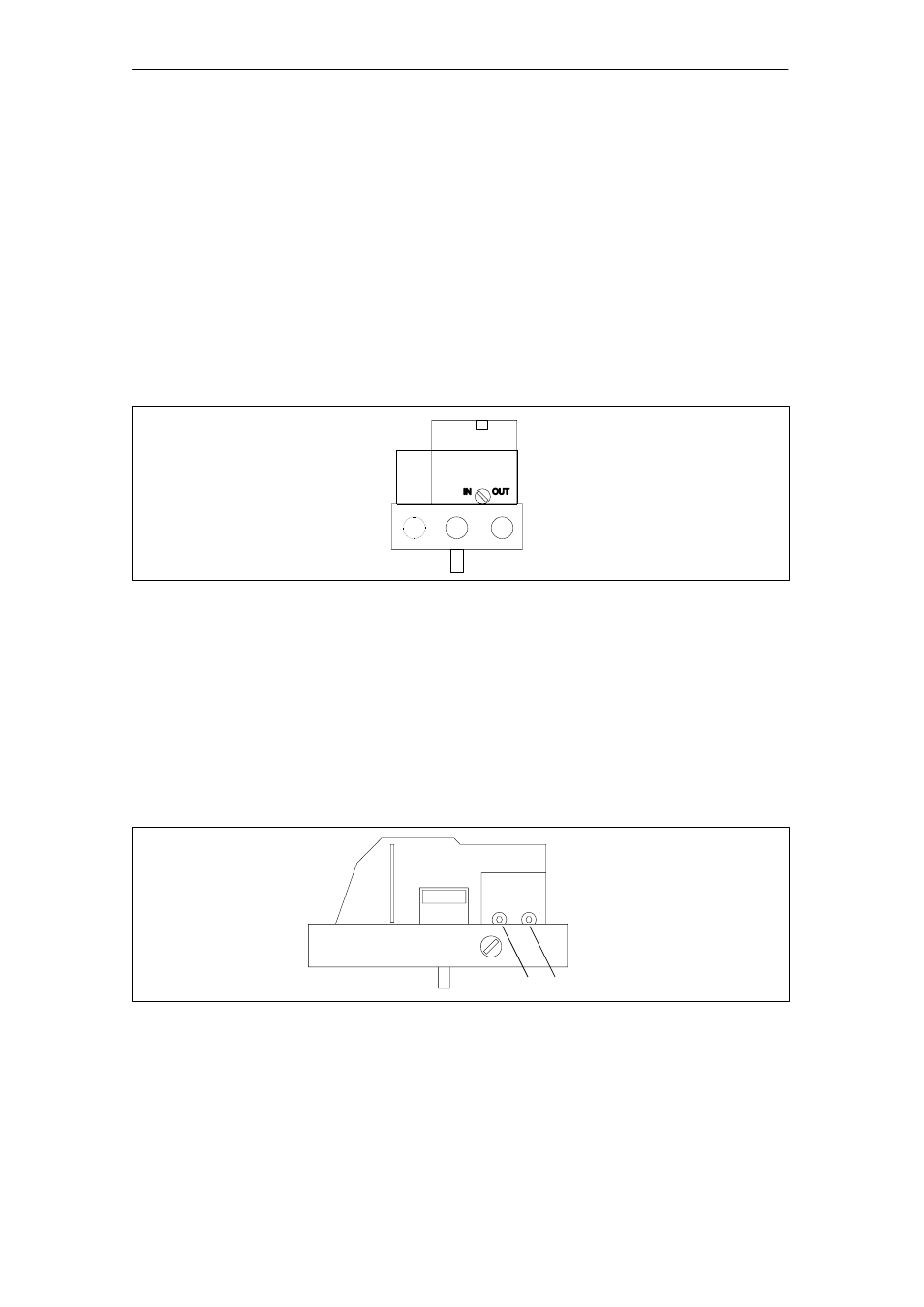
2.2.5 Purging air switchover
The purging air changeover switch above the pneumatic terminal block
(Fig. 2-5) on the valve manifold can be accessed when the housing is
open. When the switch is in position IN the interior of the housing is
purged with very small quantities of clean and dry instrument air. In po-
sition OUT the purging air is led directly out of the instrument.
Fig. 2-5
Purging air changeover switch above the pneumatic terminal block, view of the device on the
pneumatic connection side with the cover open
2.2.6 Restrictors
The air flow can be reduced with restrictors Y1 and Y2 (Fig. 2-6) to
achieve actuating times of > 1.5 s on small actuators. Turning the re-
strictors in the clockwise direction reduces the air flow until it is shut off.
To set the restrictors we recommend closing them first and then ope-
ning them again slowly (see Initialization RUN3).
Y1 Y2
Fig. 2-6
Restrictors