1 motherboard, 2 electrical connections – Moniteur 50 Series SMART Positioners User Manual
Page 21
Design and Method of Operation
2-3
Positioner SIPART PS2/SIPART PS2 PA
C79000-G7476-C150–01
8
9
3
7
9
10
4
2
1
5
6
6.2
6.1
10
3
7
90
°
33
°
11
138
8
238
**)
for double-acting
actuators
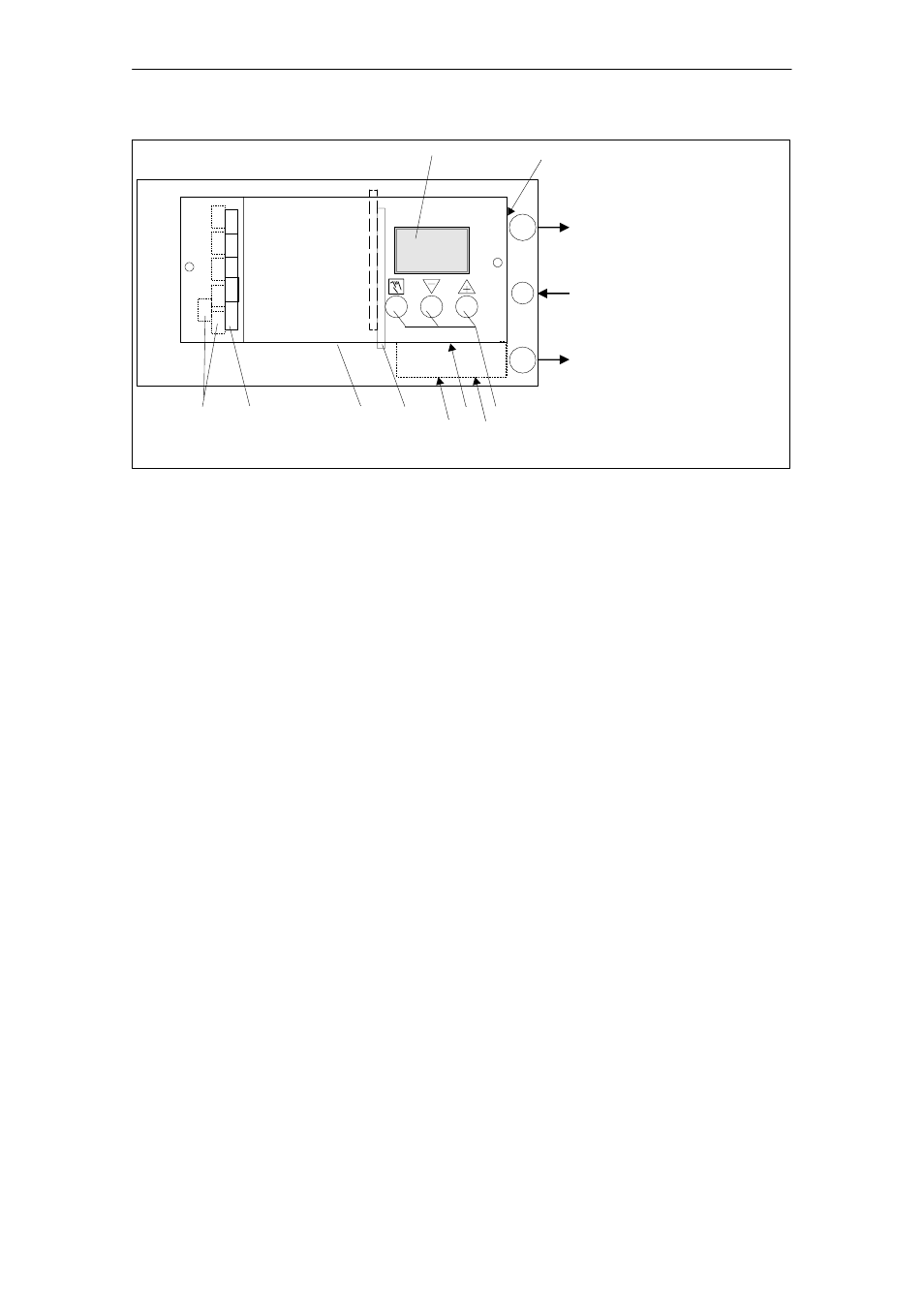
1
Input: inlet air
2
Output: positioning
pressure Y1
3
Display
4
Output: positioning
pressure Y2
**)
5
Control pushbuttons
6
Restrictor Y1
6.1
Restrictor Y1
**)
6.2
Restrictor Y2
**)
7
Transmission ratio selector
8
Adjusting wheel clutch
9
Terminals
Basic instrument
10
Terminals
Optional modules
11
Purging air selector
Fig. 2-2
View of the instrument (cover open), devices with PROFIBUS PA
2.2.1 Motherboard
The motherboard contains all electronic elements such as CPU,
memory, ADC. It also contains the display and the control pushbuttons.
The terminal blocks for connecting the option modules are also located
on the motherboard.
2.2.2 Electrical connections
The terminals of the basic instrument, the J
y
and the alarm option mo-
dule are located on the front on the left–hand side and are offset in a
step–shaped arrangement.
A cover protects the modules from being pulled out and prevents incor-
rect installation.