Juniper Systems JS600 User Manual
Page 94
Page 8-6 Technical Reference
Digital Inputs/Outputs
Do not connect digital output 1 to digital input 1, digital output 2 to digital input 2, and
digital output 3 to digital input 3 simultaneously. This configuration is used for the Reset
Connector. If you use this configuration, you will lose your files when the FieldBook is
turned on.
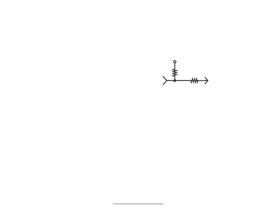
Digital Inputs
Logic Levels:
Less than 0.8V = Low (0)
Greater than 4.0V = High (1)
Default Level:
Tied high through 100K Ohm resistor
Input Protection:
100K Ohm resistor
Schematic:
Digital Outputs
Logic Levels:
0V to 5V
Low (1) = Less than 0.8V at 6 mA
High (1) = Greater than 4.0V at 6 mAHigh (1)
Powered-Down State:
The state of the outputs is undefined when the FieldBook is off.
Input Threshold
The input signal voltage threshold is approximately 1V. This input threshold allows signals
that swing between 0V and 5V, or negative to positive inputs to be used. Inputs are
protected to a maximum of +/- 25V.
Output Voltage
RS-232C outputs swing from +10V to -5V. Digital outputs are 0V to 5.0V DC.
Ring Indicator (RI) / Ring Excitation (RX)
The ring indicator wakes the FieldBook up from a powered-down state and automatically
executes a user program named RING if one exists when one of the following occurs:
- When pulsed (>200 ms) with a voltage of 5 to 25 volts (e.g. the ring excitation)
- There is a switch closure (>200 ms) between RX and RI.
The ring excitation uses the system battery voltage (5.5 to 8 V) through a protection resistor.
For more information about the serial communication port, refer to Section 2, Hardware
Features, Serial Communication Port.
+5 volts
Input
100K
100K
To input buffers