9 serial interface (si01, si02), 1 configuration, 2 control – Toshiba TMP87CP24AF User Manual
Page 82: Toshiba
Attention! The text in this document has been recognized automatically. To view the original document, you can use the "Original mode".
TOSHIBA
TMP87CM24A/P24A
2.9
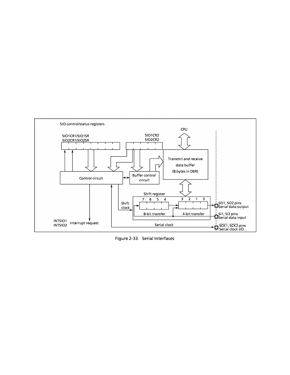
Serial Interface (SI01, SI02)
The
TMP87CM24A/P24A
each
have
two
clocked-synchronous
8-bit
serial
interfaces
(SI01
and
SI02).
Each
serial
interface
has
an
8-byte
transmit
and
receive
data
buffer
that
can
automatically
and
continuously
transfer up to 64 bits of data.
The
serial
interfaces
are
connected
to
external
devices
via
pins
P44
(SOI),
P43
(SI1),
P42
(SCK1)
for
SI01
and P47 (S02), P46 (SI2), P45 (SCK2) for SI02. The serial interface pins are also used as port P4. When
used
as
serial
interface
pins,
the
output
latches
of
these
pins
should
be
set
to
"1".
In
the
transmit
mode,
pins P43 and P46 can be used as normal I/O ports, and in the receive mode, the pins P44 and P47 can be
used as normal I/O ports.
2.9.1 Configuration
The
SI01
and
SI02
have
the
same
configuration,
except
for
the
addresses/bit
positions
of
the
control/
status registers and buffer registers.
2.9.2 Control
The
serial
interfaces
are
controlled
by
SIO
control
registers
(SI01CR1/SI01CR2
or
SI02CR1/SI02CR2).
The
serial interface status can be determined by reading SIO status registers (SI01SR or SI02SR).
The
transmit
and
receive
data
buffer
is
controlled
by
the
BUF
(bits
2
to
0
in
SI01CR2/SI02CR2).
The
data
buffer is assigned to addresses OFFO
h
to 0FF7
h
for SI01 or 0FF8
h
to OFFF
h
for SI02 in the DBR area, and
can
continuously
transfer
up
to
8
words
(bytes
or
nibbles)
at
one
time.
When
the
specified
number
of
words
has
been
transferred,
a
buffer
empty
(in
the
transmit
mode) or
a buffer
full
(in
the receive mode
or
transmit/receive mode) interrupt (INTSI01 or INTSI02) is generated.
When
the
internal
clock
is
used
as
the
serial
clock
in
the
8-bit
receive
mode
and
the
8-bit
transmit/receive
mode,
a
fixed
interval
wait
can
be
applied
to
the
serial
clock
for
each
word
transferred.
Four
different
wait times can be selected with WAIT (bits 4 and 3 in SI01CR2/SI02CR2).
3
-
24-82
2002
-
10-03