Toshiba – Toshiba TMP87CP24AF User Manual
Page 81
Attention! The text in this document has been recognized automatically. To view the original document, you can use the "Original mode".
TOSHIBA
TMP87CM24A/P24A
(3)
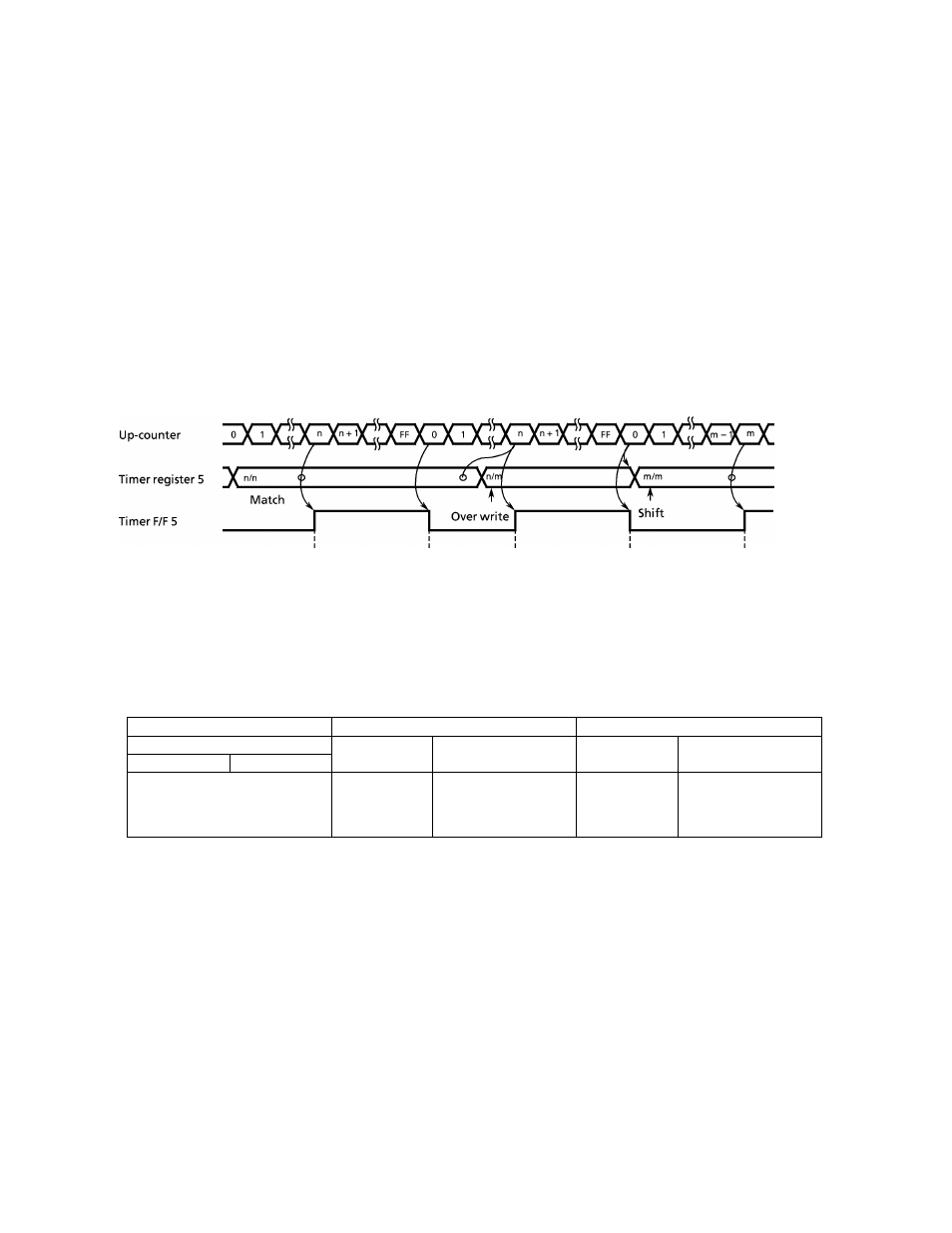
Pulse width modulation (PWM) output mode
PWM
output
with
a
resolution
of
8
-bits
is
possible.
The
internal
clock
is
used
for
counting
up.
The
contents
of
the
TREG5
is
compared
with
the
contents
of
the
up-counter.
If
a
match
is
found,
the
timer
F/F5
output
is
toggled.
The
counter
continues
counting
and,
when
an
overflow
occurs,
the
timer
F/F5
is
again
toggled
and
the
counter
is
cleared.
The
timer
F/F5
output
is
inverted
and
output
to the PWM (P41) pin. In the case of PWM output, set the P41 output latch to "1" and configure as
an output with P4CR1. An INTTC5 interrupt is generated when an overflow occurs.
TREG5
is
configured
a
2-
stage
shift
register
and,
during
output,
will
not
switch
until
one
output
cycle
is
completed
even
if
TREG5
is
overwritten;
therefore,
output
can
be
altered
continuously.
Also,
the
first time, TREG5 is shifted by setting TC5S (bit 5 in TC5CR) to "1" after data are loaded toTREGS.
Note : PWM output mode can be used in only NORMAL 1/2 or IDLE 1/2 mode.
Internal clock
PWM pin
INTTC5 interrupt
1
cycle
Figure 2-32. PWM Output Mode Timing Chart
Table 2-7. PWM Output Mode
Source clock
Resolution
Repeat cycle
NORMAL1/2, DLE1/2mode
At fc = 8MHz
At fc = 4.194304 MHz
At fc = 8MHz
At fc = 4.194304 MHz
DV7CK = 0
DV7CK= 1
fc/2^ [Hz]
500 [ns]
953.7 [ns]
128 [/.s]
244 [//s]
fc/2
250 [ns]
476.8 [ns]
64 [//s]
122
[^s]
fc
125 [ns]
238.4 [ns]
32
[^s]
61
i^s]
3
-
24-81
2002
-
10-03