Toshiba TMP87CP24AF User Manual
Toshiba, Features
Attention! The text in this document has been recognized automatically. To view the original document, you can use the "Original mode".
TOSHIBA
TMP87CM24A/P24A
CMOS 8-Bit Microcontroller
TMP87CM24AF, TMP87CP24AF
The
TMP87CM24A/P24A
are
the
high
speed
and
high
performance
8-bit
single
chip
microcomputers.
These
MCU
contain,
large
ROM,
RAM,
input/output
ports,
LCD
driver,
a
8-bit
AD
converter,
four
multi-function
timer/counters, two serial interfaces, and two clock generators on chip.
Product No.
ROM
RAM
Package
OTP MCU
TMP87CM24A
32 Kx8 bits
2Kx8bits
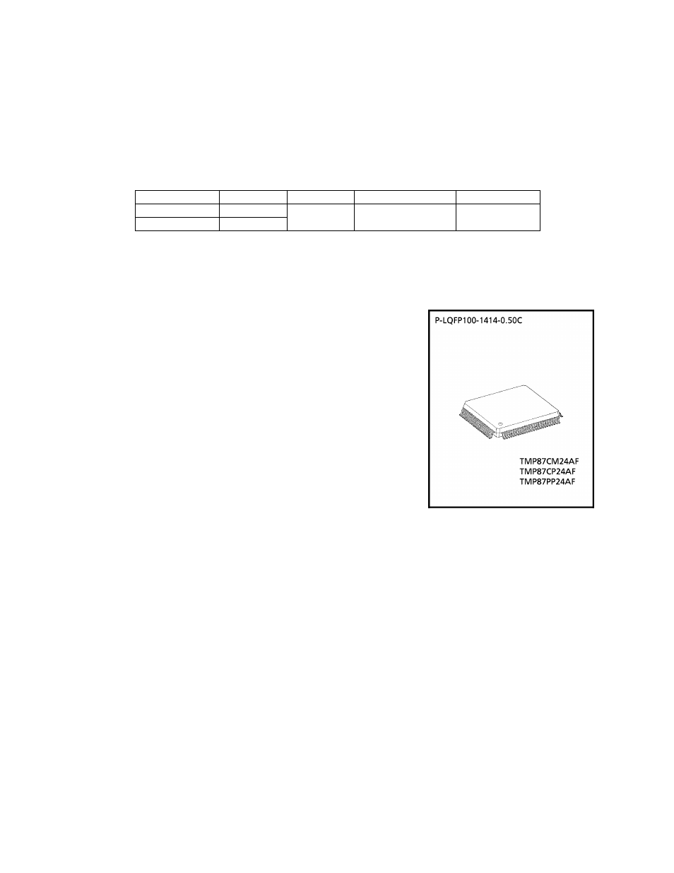
P-LQFP100-1414-0.50C
TMP87PP24A
TMP87CP24A
48 K
X
8 bits
Features
♦8-bit single chip microcomputer TLCS-870 Series
♦ instruction execution time: 0.5
jjs
(at 8 MHz), 122
jjs
(at 32 kHz)
♦ 129 types and 412 basic instructions
• Multiplication and Division (8 bitsx 8 bits, 16 bits -r 8 bits): Execution time 3.5 /
js
(at 8 MHz)
• Bit manipulations (Set/Clear/Complement/Load/Store/Test/Exclusive OR)
• 16-bit data operations
• 1-byte jump/call (Short relative jumpA/ector call)
♦ l4 interruptsources(External: 5, Internal: 9)
• All sources have independent latches each,
and nested interrupt control is available
• 4 edge-selectable external interruptswith noise reject
• High-speed task switching by register bank changeover
♦ lO-input/output ports (Max 69 pins)
♦
two
16-bit timer^ounters
• Timer, Event counter. External trigger timer. Window, PPG output
Pulse width measurement modes
♦Two 8-bit timer/counters
• Timer, Eventcounter, Capture (Pulse width/duty measurement),
PWM output, PDO modes
♦Time Base Timer (Interrupt frequency: 1 Hz to 16384 kHz)
♦ Divider output function (frequency: 1 kHz to 8 kHz)
♦watchdog Timer
♦
two
8-bit Serial Interfaces
• Each 8 bytes transmit/receive data buffer
• Internal/external serial clock, and 4-/8-bit mode
000707EBP1
I For a discussion of how the reliability of microcontrollers can be predicted, please refer to Section 1.3 of the chapter entitled
Quality and Reliability Assurance / Handling Precautions.
• TOSHIBA is continually working to improve the quality and reliability of its products. Nevertheless, semiconductor
devices in general can malfunction or fail due to their inherent electrical sensitivity and vulnerability to physical stress.
It is the responsibility of the buyer, when utilizing TOSHIBA products, to comply with the standards of safety in
making a safe design for the entire system, and to avoid situations in which a malfunction or failure of such TOSHIBA
products could cause loss of human life, bodily injury or damage to property.
In developing your designs, please ensure that TOSHIBA products are used within specified operating ranges as set
forth in the most recent TOSHIBA products specifications. Also, please keep in mind the precautions and conditions set
forth in the "Handling Guide for Semiconductor Devices," or "TOSHIBA Semiconductor Reliability Handbook" etc..
• The TOSHIBA products listed in this document are intended for usage in general electronics applications (computer,
personal equipment, office equipment, measuring equipment, industrial robotics, domestic appliances, etc.). These
TOSHIBA products are neither intended nor warranted for usage in equipment that requires extraordinarily high
quality and/or reliability or a malfunction or failure of which may cause loss of human life or bodily injury
("Unintended Usage"). Unintended Usage include atomic energy control instruments, airplane or spaceship instruments,
transportation instruments, traffic signal instruments, combustion control instruments, medical instruments, all types of
safety devices, etc.. Unintended Usage of TOSHIBA products listed in this document shall be made at the customer's
own risk.
• The products described in this document are subject to the foreign exchange and foreign trade laws.
• The information contained herein is presented only as a guide for the applications of our products. No responsibility
is assumed by TOSHIBA CORPORATION for any infringements of intellectual property or other rights of the third
parties which may result from its use. No license is granted by implication or otherwise under any intellectual
property or other rights of TOSHIBA CORPORATION or others.
• The information contained herein is subject to change without notice.
3
-
24-1
2002
-
10-03
Document Outline
- Features
- Block Diagram
- Pin Functions
- Operational Description 1. CPU Core Functions
- 1.1 Memory Address Map
- 1.2 Program Memory (ROM)
- 1.3 Program Counter (PC)
- Z)C
- ХЗЗЕОСЗЕПС
- X
- 1.4 Data Memory (RAM)
- 1.5 General-purpose Register Banks
- 1.6 Program Status Word (PSW)
- 1.6.1 Register Bank Selector (RBS)
- 1.6.2 Flags
- 1.7 Stack and Stack Pointer
- 1.7.1 Stack
- 1.7.2 Stack Pointer (SP)
- 1.8 System Clock Controller
- 1.8.1 Clock Generator
- 1.8.2 Timing Generator
- 1.8.3 Stand-by Controller
- 1.8.4 Operating Mode Control
- HI
- Z)C
- X
- X
- X
- X
- X
- X
- X
- iJHJHJijnjijnjnjnjnjnjnjijnjnjnjx
- X
- X
- X
- )€
- X
- L
- DD
- 1.10 Watchdog Timer (WDT)
- 1.10.1 Watchdog Timer Configuration
- 1.10.2 Watchdog Timer Control
- 1.10.3 Watchdog Timer Interrupt (INTWDT)
- 1.10.4 Watchdog Timer Reset
- ”L
- 1.11 Reset Circuit
- 1.11.1 External Reset Input
- 1.11.2 Address-Trap-Reset
- Z)C
- 1.11.3 Watchdog Timer Reset
- 1.11.4 System-Clock-Reset
- 2. Peripheral Hardware Functions
- 2.1 Special Function Registers (SFR) and Data Buffer Registers (DBR)
- 2.2 I/O Ports
- 2.2.1 Port PO (P07 to POO)
- 2.2.2 PortPI (P17to P10)
- 2.2.3 Port P2 (P22 to P20)
- 2.2.4 Port P3 (P35 to P30)
- 2.2.5 Port P4 (P47 to P40)
- 2.2.6 Port P5 (P57 to P50)
- 2.2.7 Ports P6 (P67 to P60) Port P7 (P77 to P70) Port P8 (P87 to P80) Port P9 (P93 to P90)
- 2.3 Time Base Timer (TBT)
- 2.4 Divider Output (DVO)
- 2.5.2 Control
- 2.5.3 Function
- I)GZ)GZ)C2:XiZ)GZn^XHXZDGZ)(
- X
- 11
- À
- 2.6 16-Bit Timer/Counter 2 (TC2)
- 2.6.1 Configuration
- 2.6.2 Control
- 2.6.3 Function
- 2.7 8-Bit Timer/Counter 3 (TC3)
- 2.7.1 Configuration
- 2.7.2 Control
- 2.7.3 Function
- Ш1ЛЛДДЛЛДДЛЛЛЛДДЛЛЛЛГ
- я
- я
- я
- X
- X
- 7
- X