Input/output circuitry, Toshiba – Toshiba TMP87CP24AF User Manual
Page 110
Attention! The text in this document has been recognized automatically. To view the original document, you can use the "Original mode".
TOSHIBA
TMP87CM24A/P24A
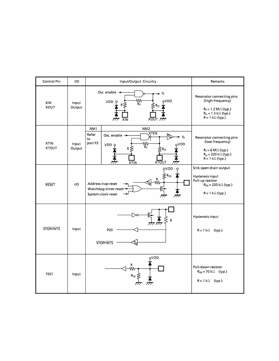
Input/Output Circuitry
(1) Control pins
The input/output circuitries of the TMP87CM24A/P24A control pins are shown below.
Please
specify
eitherthe
single-clock
mode
orthe
dual-clock
mode
by
a
code
(NM1
or
NM2)
as
an
option
for an operating mode during reset.
Note 1:
The TEST pin of the TMP87PP24A does not have a pull-down resistor. Be sure to fix the
TEST pin to low in MCU mode.
Note2 :
The TMP87PP24A is placed in the single-clock mode during reset.
3
-
24-110
2002
-
10-03
This manual is related to the following products: