3 function, Toshiba – Toshiba TMP87CP24AF User Manual
Page 67
Attention! The text in this document has been recognized automatically. To view the original document, you can use the "Original mode".
TOSHIBA
TMP87CM24A/P24A
2.5.3 Function
Timer/counter
1
has
six
operating
modes:
timer,
external
trigger
timer,
event
counter,
window,
pulse
width measurement, programmable pulse generator output mode.
(1)
Timer Mode
In
this
mode,
counting
up
is
performed
using
the
internal
clock.
The
contents
of
TREG1A
are
compared
with
the
contents
of
up-counter.
If
a
match
is
found,
an
INTTC1
interrupt
is
generated,
and
the
counter
is
cleared
to"0".
Counting
up
resumes
after
the
counteriscleared.
The
current
contents
of
up-counter
can
be
transfered
to
TREG1B
by
setting
SCAP1
(bit
6
in
TC1CR)
to
"1"
(software capture function). SCAP1 is automatically cleared to "0" after capaturing.
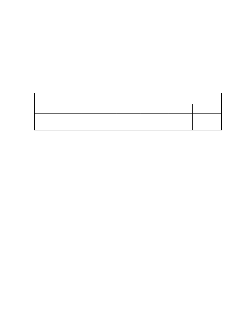
Table 2-3. Timer/Counter 1 Source Clock (Internal Clock)
Source clock
Resolution
Maximum time setting
NORMAL1/2, IDLE1/2 modes
SLOW, SLEEP modes
Atfc = 8MHz
At fs = 32.768 kHz
Atfc = 8MHz
At fs = 32.768 kHz
DV7CK = 0
DV7CK= 1
fc/2" [Hz]
fs/2^ [Hz]
fs/2^ [Hz]
256
JUS
244.14
juS
16.8 s
16.0 s
fc/2'
fc/2'
-
16
jtS
-
1.0 s
-
fc/2^
fc/2^
-
1
piS
-
65.5 ms
-
Example 1 : Sets the timer mode with source clock fs/23[Hz] and generates an interrupt 1 s. later (at
fs = 32.768 kHz).
LD
(TC1CR),00000000B
; Sets the TCI mode and source clock
LDW
(TREG1A), 1000H
; Sets the timer register
( 1
s^23/fs =
ioo
O
h
)
SET
El
LD
(EIRL).EF4
; enable INTTC1
(TCI CR), 0001OOOOB
; Starts TCI
Note :
TC1CR is a write-only register, which cannot start by [SET(TC1CR).4] instruction.
Example 2 : Software capture
LD
LD
(TC1CR),01010000B
WA, (TREG1B)
; SCAPI<-1 (Captures)
; Reads captured value
3
-
24-67
2002
-
10-03