Appendix b - vfd information (cont), Vfd operation, Vfd modes – Carrier 48/50PD05 User Manual
Page 83
83
APPENDIX B - VFD INFORMATION (CONT)
VFD Operation
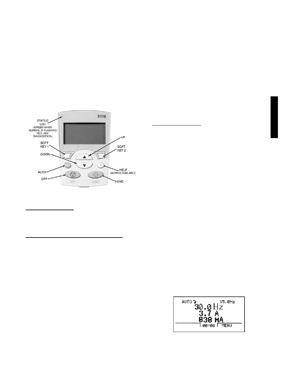
The VFD keypad is shown in Fig. 41. The function of SOFT
KEYS 1 and 2 change depending on what is displayed on the
screen. The function of SOFT KEY 1 matches the word in the
lower left--hand box on the display screen. The function of SOFT
KEY 2 matches the word in the lower right--hand box on the
display screen. If the box is empty, then the SOFT KEY does not
have a function on that specific screen. The UP and DOWN keys
are used to navigate through the menus. The OFF key is used to
turn off the VFD. The AUTO key is used to change control of the
drive to automatic control. The HAND key is used to change
control of the drive to local (hand held) control. The HELP button
is used to access the help screens.
For the VFD to operate on the 48/50PD units, the drive must be set
in AUTO mode. The word “AUTO” will appear in the upper left
hand corner of the VFD display. Press the AUTO button to set the
drive in AUTO mode.
C08675
Fig. 41 -- VFD Keypad
Start Up with Assistant
Initial start--up has been performed at the factory. Use of the start
up assistant will override factory VFD configurations. See below
to check that all parameters listed in VFD Configurations table are
correctly configured on the VFD.
Start Up by Changing Parameters Individually
Initial start--up is performed at the factory. To start up the VFD
with by changing individual parameters, perform the following
procedure:
1. Select MENU (SOFT KEY 2). The Main menu will be
displayed.
2. Use the UP or DOWN keys to highlight PARAMETERS
on the display screen and press ENTER (SOFT KEY 2).
3. Use the UP or DOWN keys to highlight the desired
parameter group and press SEL (SOFT KEY 2).
4. Use the UP or DOWN keys to highlight the desired
parameter and press EDIT (SOFT KEY 2).
5. Use the UP or DOWN keys to change the value of the
parameter.
6. Press SAVE (SOFT KEY 2) to store the modified value.
Press CANCEL (SOFT KEY 1) to keep the previous value.
Any modifications that are not saved will not be changed.
7. Choose another parameter or press EXIT (SOFT KEY 1) to
return to the listing of parameter groups. Continue until all
the parameters have been configured and then press EXIT
(SOFT KEY 1) to return to the main menu.
IMPORTANT: The current parameter value appears above the
highlight parameter. To view the default parameter value, press the
UP and DOWN keys simultaneously. To restore the default factory
settings, select the application macro “HVAC Default.”
VFD Modes
The VFD has several different modes for configuring, operating,
and diagnosing the VFD. The modes are:
S
Standard Display mode ⎯ shows drive status information and
operates the drive
S
Parameters mode ⎯ edits parameter values individually
S
Start--up Assistant mode ⎯ guides the start up and
configuration
S
Changed Parameters mode ⎯ shows all changed parameters
S
Drive Parameter Backup mode ⎯ stores or uploads the
parameters
S
Clock Set mode ⎯ sets the time and date for the drive
S
I/O Settings mode ⎯ checks and edits the I/O settings
Standard Display Mode
Use the standard display mode to read information on the drive
status and operate the drive. To reach the standard display mode,
press EXIT until the LCD display shows status information as
described below. See Fig. 42.
The top line of the LCD display shows the basic status information
of the drive. The HAND icon indicates that the drive control is
local from the control panel. The AUTO icon indicates that the
drive is in remote control mode, such as the basic I/O (X1) or field
bus.
The arrow icon indicates the drive and motor rotation status. A
rotating arrow (clockwise or counterclockwise) indicates that the
drive is running and at set point and the shaft direction is forward
or reverse. A rotating blinking arrow indicates that the drive is
running but not at set point. A stationary arrow indicates that the
drive is stopped. For Carrier rooftop units, the correct rotation is
counterclockwise.
The upper right corner shows the frequency set point that the drive
will maintain.
Using parameter group 34, the middle of the LCD display can be
configured to display 3 parameter values. The default display
shows parameters 0103 (OUTPUT FREQ) in percentages, 0104
(CURRENT) in amperes, and 0120 (AI1) in milliamperes.
The bottom corners of the LCD display show the functions
currently assigned to the two soft keys. The lower middle displays
the current time (if configured to show the time).
The first time the drive is powered up, it is in the OFF mode. To
switch to local hand--held control and control the drive using the
control panel, press and hold the HAND button. Pressing the
HAND button switches the drive to hand control while keeping the
drive running. Press the AUTO button to switch to remote input
control. To start the drive press the HAND or AUTO buttons, to
stop the drive press the OFF button.
C08676
Fig. 42 -- Standard Display Example
48/
50P
D