General, Basic control usage, Comfort link control – Carrier 48/50PD05 User Manual
Page 3: Scrolling marquee, Accessory navigator display, Operation
3
GENERAL
This publication contains Start--Up, Controls, Operation, Service,
and Troubleshooting information for the 48/50PD rooftop units.
(See Table 1.) These units are equipped with ComfortLinkt
controls version 1.X or higher and use Puronr refrigerant. The
specific base unit installation instructions and/or wiring label
diagram may also be required in conjunction with this book as a
guide to a specific unit on the roof. All the units in Table 1 are
Displacement Ventilation or Single Zone Variable Airflow units
that provide stand--alone or network operation.
Table 1 — Rooftop Units
MODEL
SIZE
NOMINAL TONS
48/50PD
05
4
06
5
BASIC CONTROL USAGE
ComfortLink Control
The ComfortLink control is a comprehensive unit-management
system. The control system is easy to access, configure, diagnose
and troubleshoot.
The ComfortLink control is fully communicating and cable-ready
for connection to the Carrier Comfort Network® (CCN) building
management
system.
The
control
provides
high-speed
communications for remote monitoring via the Internet. Multiple
units can be linked together (and to other ComfortLink control
equipped units) using a 3-wire communication bus.
The ComfortLink control system is easy to access through the use
of a unit-mounted display module. There is no need to bring a
separate computer to this unit for start-up. Access to control menus
is simplified by the ability to quickly select from 11 menus. A
scrolling readout provides detailed explanations of control
information. Only four, large, easy-to-use buttons are required to
maneuver through the entire controls menu. The display readout is
designed to be visible even in bright sunlight.
For
added
service
flexibility,
an
accessory
hand-held
Navigator™ module is also available. This portable device has an
extended communication cable that can be plugged into the unit’s
communication network at the main control box. The Navigator
display provides the same menu structure, control access and
display data as is available at the unit-mounted Scrolling Marquee
display.
Run Status
Service Test
Temperature
Pressures
Setpoints
Inputs
Outputs
Configuration
Time Clock
Operating Modes
Alarms
Alarm Status
ENTER
MODE
ESCAPE
C06320
Fig. 1 -- Scrolling Marquee
Scrolling Marquee
This device is the keypad interface used to access the control
information, read sensor values, and test the unit. The Scrolling
Marquee is located in the main control box and is standard on all
units. The Scrolling Marquee display is a 4-key, 4-character,
16-segment LED (light-emitting diode) display module. The
display also contains an Alarm Status LED. (See Fig. 1.)
The display is easy to operate using 4 buttons and a group of 11
LEDs that indicate the following menu structures:
S
Run Status
S
Service Test
S
Temperatures
S
Pressures
S
Set points
S
Inputs
S
Outputs
S
Configuration
S
Timeclock
S
Operating Modes
S
Alarms
Through the Scrolling Marquee, the user can access all of the
inputs and outputs to check on their values and status, configure
operating parameters plus evaluate the current decision status for
operating modes. The control also includes an alarm history which
can be accessed from the display. In addition, through the Scrolling
Marquee, the user can access a built-in test routine that can be used
at start-up commissioning and to diagnose operational problems
with the unit.
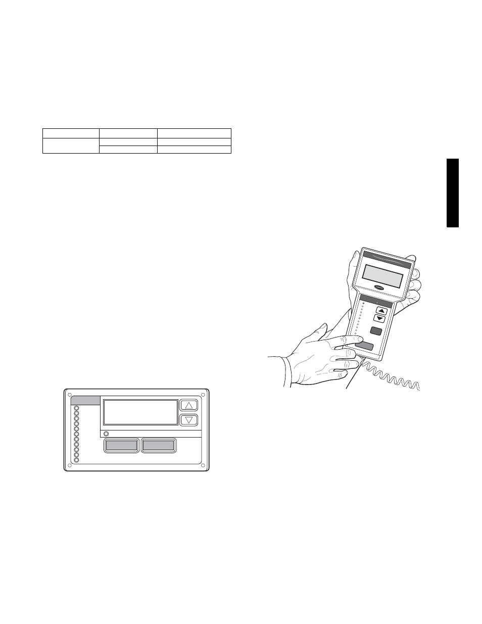
Accessory Navigator Display
The accessory hand-held Navigator display can be used with the
48/50PD units. (See Fig. 2.) The Navigator display operates the
same way as the Scrolling Marquee device. The Navigator display
is plugged into the LEN (local equipment network) port on either
TB1 or the J3 port on the ECB (economizer control board).
Run Sta
tus
Service
Test
Temper
ature
s
Pres
sures
Setpo
ints
Inputs
Outp
uts
Config
uration
Time C
lock
Operating
Modes
Alarm
s
E NTE
R
E S C
M O D
E
Alarm
Sta
tus
TIME
EWT
LWT
SETP
1 2 . 5 8
5 4 . 6 °F
4 4 . 1 °F
4 4 . 0 °F
N A V
I G A
T O R
C o m f o
r t
L i n k
C06321
Fig. 2 -- Accessory Navigator Display
Operation
All units are shipped from the factory with the Scrolling Marquee
display, which is located in the main control box. (See Fig. 1.) In
addition, the ComfortLink control also supports the use of the
handheld Navigator display.
Both displays provide the user with an interface to the
ComfortLink control system. The displays have up and down
arrow keys, an ESCAPE key and an ENTER key. These keys are
used to navigate through the different levels of the display
structure. The Navigator display and the Scrolling Marquee operate
in the same manner, except that the Navigator display has multiple
lines of display and the Scrolling Marquee has a single line. All
further discussions and examples in this document will be based on
the Scrolling Marquee display. See Table 2 for the menu structure.
The four keys are used to navigate through the display
structure, which is organized in a tiered mode structure. If the
buttons have not been used for a period, the display will default to
the AUTO VIEW display category as shown under the RUN
STATUS category. To show the top-level display, press the
ESCAPE key until a blank display is shown. Then use the up and
48/
50P
D