Gas valve adjustment, Puron r refrigerant, In. pipe plug and screw cap – Carrier 48/50PD05 User Manual
Page 65
65
The TXV is set to maintain between 10 and 15 degrees of
superheat at the compressors. The valves are factory set and cannot
be adjusted. Do not use A TXV designed for use with R--22.
R4
R410A RE
REFRI
RIGERANT
RANT
OUTDOOR F
R FAN M
N M UST BE OPERATING ON H
N HIGH S
H SPEED
20
20
40
40
60
60
80
80
10
100
12
120
14
140
16
160
150
150
200
200
25
250
300
00
350
350
400
400
450
450
500
500
550
550
600
600
Co mp re ss
ssor Disc
isc h a rg e P re ss
ssu re , [p sig
sig]
Add
dd Cha
harge if Abov
bove the
the Cur
urve
Rem ove
ve Ch
Char
arge if
if Belo
low the Cu
Curve
ve
OutdoorO
u
td
o
o
r
CoilC
o
il
L
eavine
a
vi
n
g
Te
m
p
Te
m
p
eratue
ra
tu
re,re
,
[Deg[D
e
g
reesre
e
s
F]F
]
C07040
Fig. 35 -- Charging Chart ⎯ 48/50PD05
R4
R410A RE
REFRI
RIGERANT
RANT
OUTDOOR F
R FAN M
N M UST BE OPERATING ON H
N HIGH S
H SPEED
20
20
40
40
60
60
80
80
10
100
12
120
14
140
16
160
150
150
200
200
25
250
300
00
350
350
400
400
450
450
500
500
550
550
600
600
Co mp re ss
ssor Disc
isc h a rg e P re ss
ssu re , [p sig
sig]
Add
dd Cha
harge if Abov
bove the
the Cur
urve
Rem ove
ve Ch
Char
arge if
if Belo
low the Cu
Curve
ve
OutdoorO
u
td
o
o
r
CoilC
o
il
L
eavine
a
vi
n
g
Te
m
p
Te
m
p
eratue
ra
tu
re,re
,
[Deg[D
e
g
reesre
e
s
F]F
]
C07041
Fig. 36 -- Charging Chart ⎯ 48/50PD06
PuronR Refrigerant
Puron refrigerant operates at 50 to 70 percent higher pressures than
R-22. Be sure that servicing equipment and replacement
components are designed to operate with Puron refrigerant. Do not
mix with components that have been used with other refrigerants.
Puron refrigerant, as with other HFCs, is only compatible with
POE oils.
Recovery cylinder service pressure rating must be 400 psig. Puron
systems should be charged with liquid refrigerant. Use a
commercial-type metering device in the manifold hose. Manifold
sets should be 750 psig high-side and 200 psig low-side with 520
psig low-side retard. Use hoses with 750 psig service pressure
rating. Leak detectors should be designed to detect HFC
refrigerant.
Table 26 — Altitude Compensation*
48PG03--07
ELEVATION
(ft)
NATURAL GAS
ORIFICE†
PROPANE
ORIFICE†
0-1,999
45
52
2,000
47
52
3,000
47
53
4,000
47
53
5,000
48
53
6,000
48
53
7,000
48
53
8,000
49
54
9,000
49
54
10,000
50
54
11,000
51
54
12,000
51
55
13,000
52
55
14,000
52
56
*As the height above sea level increases, there is less oxygen per cubic foot of air.
Therefore, heat input rate should be reduced at higher altitudes. Includes a 4% input
reduction per each 1000 ft.
† Orifices available through your Carrier dealer.
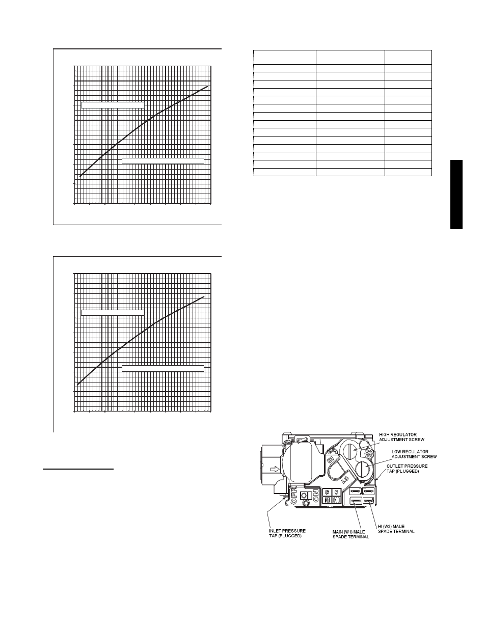
Gas Valve Adjustment
The gas valve opens and closes in response to the thermostat or
limit control.
When power is supplied to valve terminals W2 (High Fire) and C1,
the main valve opens to its preset position.
The regular factory setting is stamped on the valve body.
To adjust regulator:
1. Set unit at setting for no call for heat.
2. Turn main gas valve to OFF position.
3. Remove
1
/
8
-in. pipe plug from manifold pressure tap
connection. Install a suitable pressure-measuring device.
4. Set main gas valve to ON position.
5. Set thermostat at setting to call for heat.
6. Remove screw cap covering regulator adjustment screw.
(See Fig. 37.)
7. Turn adjustment screw clockwise to increase pressure
or
counterclockwise to decrease pressure. The setting is 3.50
in. wg on sizes 03-14 and 3.00 on size 16--28.
8. Once desired pressure is established, set unit setting for no
call for heat, turn off main gas valve, remove
pressure-measuring device, and replace
1
/
8
-in. pipe plug and
screw cap.
C08663
Fig. 37 -- 48PD Gas Valve
48/
50P
D