Ection, 14 – c, Hannel – Rice Lake MSI-9850 CellScale RF Digital Indicator - Operator Manual User Manual
Page 90: Etup, Alibration, Channel setup menu, Msi-9850
Page 90 MSI-9850 RF Remote Indicator • User Guide
MSI-9850
HANDHELD RF REMOTE INDICATOR for
C
ELL
S
CALE
®
SECTION 14 – CHANNEL SETUP & CALIBRATION
CHANNEL SETUP MENU
CHANNEL FILTER
1 Off
2 Low
3 High
1 Channel INACTIVE
1 Channel is ACTIVE
CALIBRATE -CHN-
SETTINGS
1 Motion Band 0d
2 Standard INDUSTRY
3 Center of Zero OFF
4 AutoZero (AZM) OFF
5 AZM Band 1d
Starts the Calibration
Procedure
3 Center of Zero OFF
3 Center of Zero ON
SET MOTION BAND (d)
ESC exits no change
ENTER saves value
0-9 replaces value
10
min = 0 max = 255
^ incs, v decs digit
SCALE CAL STANDARD
1 Industrial (unreg)
2 NIST NTEP
3 OIML R76
4 Industrial Metric
4 AutoZero (AZM) OFF
4 AutoZero (AZM) ON
AUTOZERO BAND (d)
ESC exits no change
ENTER saves value
0-9 replaces value
10
min = 0 max = 255
^ incs, v decs digit
5 Zero RUSure Msg OFF
5 Zero RUSure Msg ON
CHANNEL / CALIBRATION
--Channel Name--
--Chn-- --Index--
1 Channel is ACTIVE
2 Filter LOW
3 Calibrate Settings
4 Start Calibration
5 Zero RUSure Msg ON
Changes to the
next Channel
available
Shortcut
CHANNEL / CALIBRATION
--Channel Name--
--Chn-- --Index--
CALIBRATE 1-1
SETTINGS
CHANNEL FILTER
SET MOTION BAND (d)
SCALE CAL STANDARD
AUTOZERO BAND (d)
ESC
!
SETUP
2
DEF
1
ABC
3
GHI
5
MNO
4
JKL
7
STU
F2
CHANNEL
1
ABC
2
DEF
3
GHI
4
JKL
1
ABC
F2
CHANNEL
5
MNO
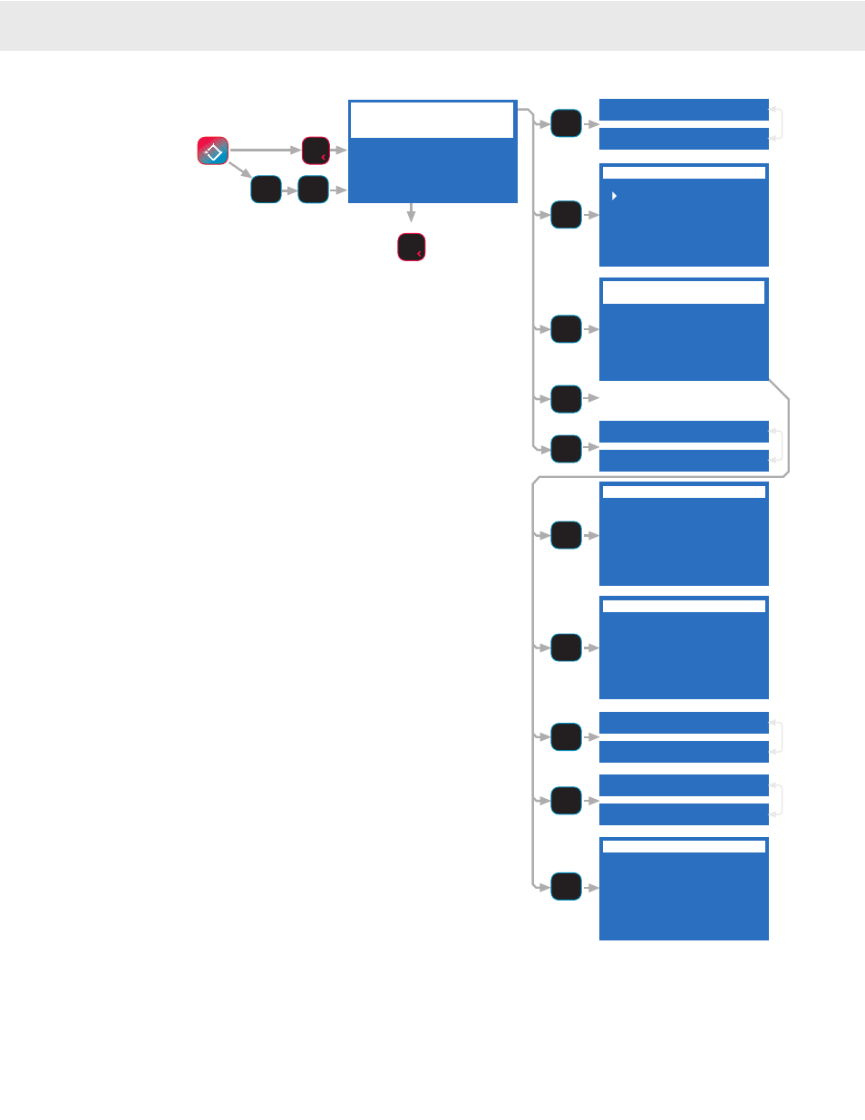
The Channel Setup Menu provides control of Channel settings in
the CellScale. The CHANNEL / CALIBRATION menu screen
will display the current channel name (if it was provided in the
CellScale), channel number and scan list index number.
[1]
Channel is ACTIVE / INACTIVE – The Channel is operat-
ing as part of the Scan List if ACTIVE. If set INACTIVE, the
channel will not be available to any device in the Network,
and will not be displayed on the 9850.
[2]
Filter – Each A/D channel has independent filtering set by
this menu. Set “Off” for normal scales, Low or High for
scales that are subject to a lot of movement or vibration, or
for very high resolution scales. This menu is locked out in
L-F-T systems until the calibration switch is enabled at the
CellScale. Advanced settings for filtering must be performed
in the Master CellScale.
[3]
Calibrate Settings – See following submenu description.
This menu is locked out in L-F-T systems until the calibra-
tion switch is enabled at the CellScale.
[4]
Start Calibration – Starts the Calibration Procedure. This
menu is locked out in L-F-T systems until the calibration
switch is enabled at the CellScale.
CALIBRATE SETTINGS
[1]
Motion Band – The motion band determines the range of
weight variation that the indicator considers to be stable
weight. Selecting “Motion Band” calls a numeric entry
screen.
[2]
Scale Cal Standard – The submenu has 4 choices: Industrial
[1]
No limits on settings. NIST NTEP
[2]
Settings limited
to NTEP ranges, calibration is protected by the CellScale
Sealed Switch. OIML R76
[3]
Settings limited to R76
ranges, only metric units allowed. Industrial Metric
[4]
Same as 1 except only metric units allowed.
[3]
Center of Zero ON/OFF – Enables the Center of Zero
annunciator. The scale is within 1/4 d of center when the
annunciator is on.
[4]
Autozero (AZM) ON/OFF – Enables and disables Auto
Zero Maintenance (AZM).
[5]
Autozero Band – Calls a numeric entry screen to set up the
range of weight in ‘d’ that is automatically zeroed. Typical
settings for the AZM band are ±1d for most applications, ±3d
for truck scales, and ±.6d for L-F-T applications (reached
by setting the band to 0)
Go to Index