Aux power and switches, Aux power, remote switches, remote led connection – Rice Lake MSI-9850 CellScale RF Digital Indicator - Operator Manual User Manual
Page 13
MSI CellScale
®
System • 9850 User Guide Page 13
MEASUREMENT SYSTEMS INTERNATIONAL
Firmware Version 5-XX for 2450 Modems
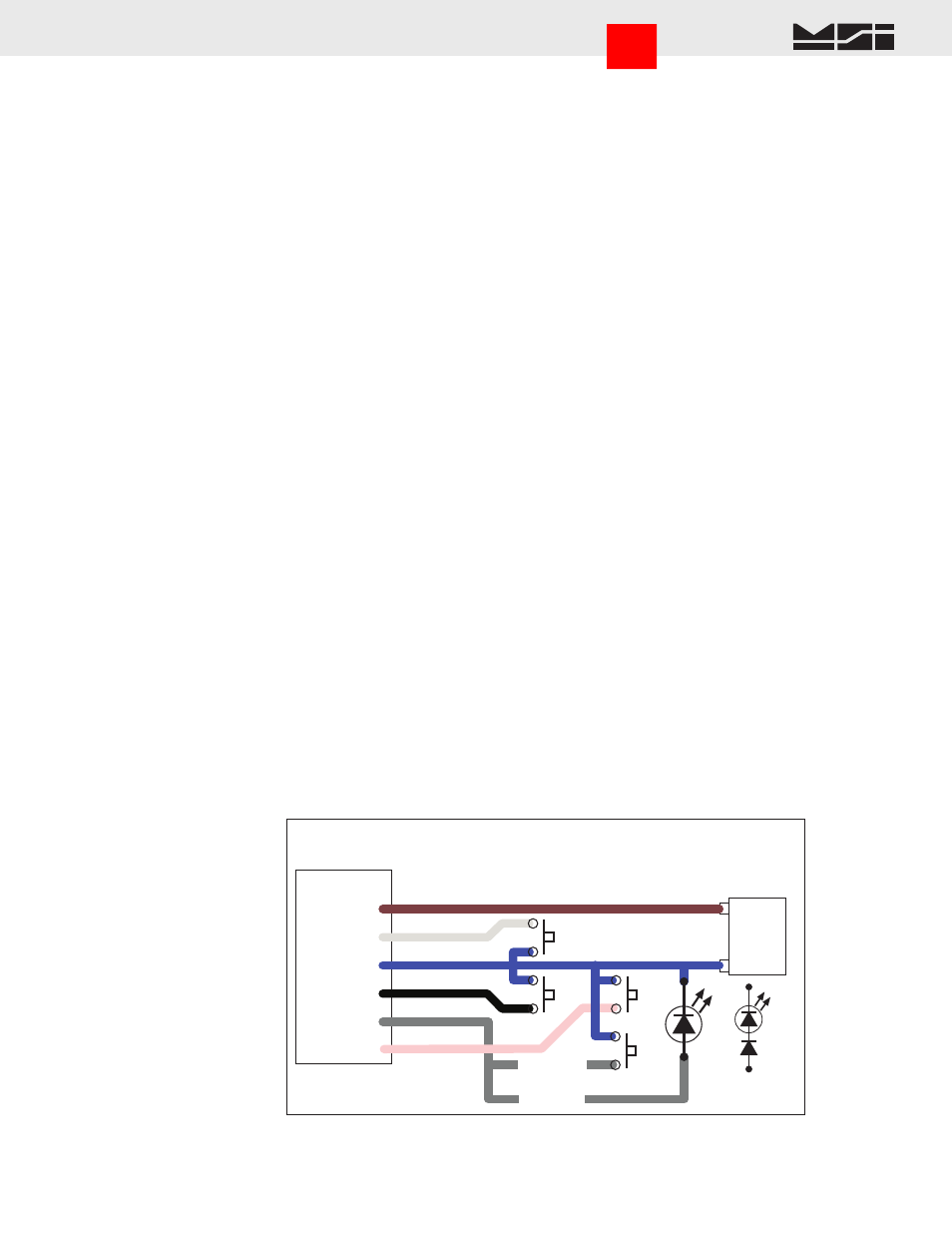
9850 P2
PWR PORT
Pin 1- Vin+
Pin 2 - SW1
Pin 3 - GND
Pin 4 - SW2
Pin 5 - LED
or
SW4
SW1
Aux Power, Remote Switches, Remote LED Connection
Aux Battery or
Power Supply
Power
Source
6-25Vdc
+
–
SW2
Momentary Switches Only
BRN
WHT
BLUE
BLK
GREY
Pin 6 - SW3
PINK
SW3
SW4
FOR LED
FOR SW4
or
LED
Silicon
Diode
Add Diode
to allow LED
and SW4
LED
Insulate all unused wires.
Green
Connect to Earth Ground.
The negative input and earth ground are isolated internally in the 9850. However, the negative output of the Isolated DC supply is common to the chassis ground. Some
systems may require isolating the chassis of the 9850 to avoid ground loops. In this case, the Green wire should be insulated and not connected to earth ground.
The 9850’s Isolated DC Supply is protected by an internal Fuse. Panel fusing, if necessary, shoud be 1.5A @12Vdc,
3/4A @ 24V, or 3/8A @ 48V. Due to power on surge currents, slightly increased fuse ratings might be needed,
or use a slow or medium blow fuse type. Total DC input power consumption of the 9850 is below 12 watts, and
is typically 7-8 watts.
AUX POWER AND SWITCHES
Aux Power is supplied through a pre-assembled cable (MSI P/N 13195). It provides for DC power in (7-25Vdc),
up to four switches, and a remote LED indicator. The LED indicator provides a remote indication that the 9850
is on and functioning. The switches and LED are supplied by the end user. In combination with the Set Points
Cable, the switch inputs can also be used with standard Isolated Input Modules.
Blue
Connect to Battery Negative or supply ground. It is generally best to connect this directly to the battery
or Power Supply negative terminal, or where the negative terminal is attached to the chassis.
Brown Connect to Battery or Power Supply Positive (7-25VDC). Again, a direct battery connection is usually
best to avoid interference with vehicle electrical systems. The CellScale is internally fused. If connected
to a breaker or fuse panel, use 2A at 12V, 1A at 24V. Fast blow or medium blow fuses are acceptable.
White Switch 1 input. Connect to a Normally Open push-button switch. The other switch terminal must con-
nect to the Blue wire (ground). If this feature is not used, insulate the end of the wire to prevent it from
shorting.
Black Switch 2 input. Connect to a Normally Open push-button switch. The other switch terminal must con-
nect to the Blue wire (ground). If this feature is not used, insulate the end of the wire to prevent it from
shorting.
Pink
Switch 3 input. Connect to a Normally Open push-button switch. The other switch terminal must con-
nect to the Blue wire (ground). If this feature is not used, insulate the end of the wire to prevent it from
shorting.
Gray Switch 4 input and/or Remote power indication. Connect to the anode of a remote LED. The LED cathode
must connect to the Blue wire (ground). No current limit resistor is required, current drive is provided by
the CellScale (~15mA). Suitable for LEDs with VF 1.6V to 2.4V@ 20mA. Not suitable for Blue or White
LEDs due to their VF >3V. If a fourth switch input is needed, connect to a Normally Open push-button
switch. If this wire is not used, insulate the end of the wire to prevent it from shorting. It is possible to
have the external LED in parallel with SW4. To do this, place a silicon diode (1N4148 or equivalent) in
series with the LED and place the Diode LED assembly across the switch. The current to the LED will
reduce to ~ 9mA (using a AlGaAs Red LED).
Go to Index