Set points output, Multi-drop output – Rice Lake MSI-9850 CellScale RF Digital Indicator - Operator Manual User Manual
Page 15
MSI CellScale
®
System • 9850 User Guide Page 15
MEASUREMENT SYSTEMS INTERNATIONAL
Firmware Version 5-XX for 2450 Modems
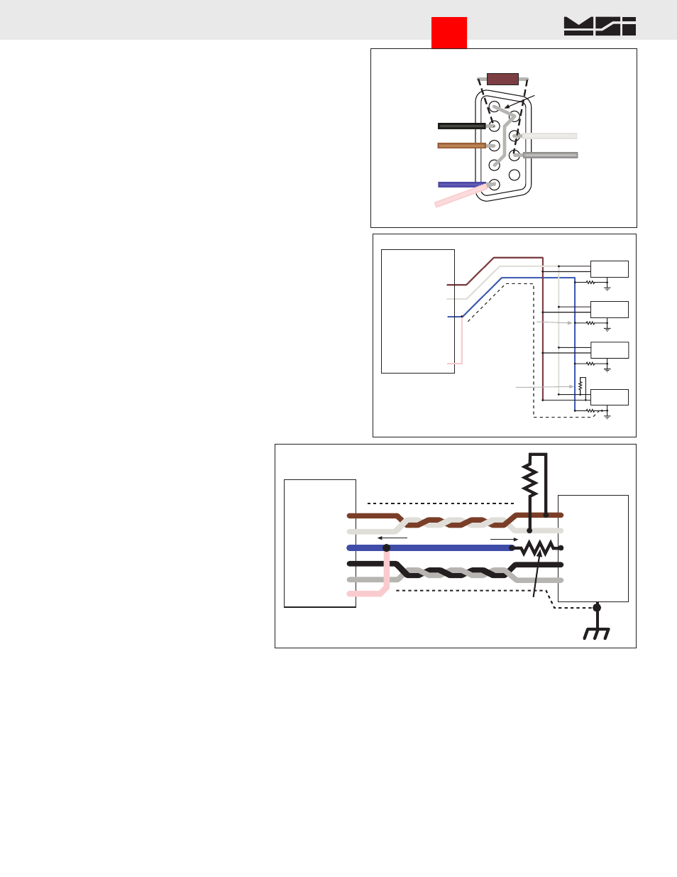
Both RS-422 and RS-485 are multi-drop capable.
The 9850 can drive up to 32 receivers on one
twisted pair. Although the 9850 uses standard RS-
485 drivers, the 9850 firmware does not have a full
duplex protocol. Contact MSI for custom solutions
for networking with RS-485.
Comm Port Cable Color Code RS-422/485
Applies to Comm Port 1 Only
Brown TD- (Z)
White TD+ (Y)
Black RD+ (A)
Grey RD- (B)
Blue
Signal Ground
Pink
Ground (to Blue) to configure port for
422/485
Drain Wire Connect to metal shell.
If the 9850 is the final device in a chain, enable
the termination resistor (see Comm Port Menus).
Install a 120Ω resistor at the end of the cable across
RD+ and RD-.
485
Receiver
485
Receiver
485
Receiver
485
Receiver
BROWN
WHITE
BLUE
Shield Drain
485 Termination
Resistor.
120
Ω 1/4W
Final receiver
only.
Terminate Shield
at only one end.
Multi-drop Output
+
–
+
–
+
–
Gnd Pink
Wire to enable
422/485 Mode
+
–
9850
COMM PORT 1
Pin 1 - TD- (Z)
Pin 2 - TD+ (Y)
Pin 3 - GND
Pin 4 - RD+
Pin 5 - RD-
Pin 6 - Mode
PINK
9850
COMM PORT 1
Pin 1- TD- (Z)
Pin 2 - TD+ (Y)
Pin 3 - GND
Pin 4 - RD+ (A)
Pin 5 - RD- (B)
TD+
TD-
RD-
RD+
GND
CHASSIS
GND
If the 9850 is the
final receiver, enable
the internal termination
(Menu choice).
485 Termination
Resistor. 120
Ω 1/4W
Final receiver only.
Terminate Shield
at only one end.
Ground Reference
Resistor. 100
Ω 1/2W
At all receivers.
Shield
Shield
RS-485/422 Full Duplex Connection
Remote Device
Up to 1000 meters
BRN
WHT
BLUE
BLK
GREY
Pin 6 - Mode
PINK
9850 COMM 1 only
SET POINTS OUTPUT
Set Points Output Cable
The 9850 can directly drive up to 5 external relays which correspond to the CellScale system Set Points 1-5. The
open drain MOSFET output lines are transient and inductive kickback protected so that no snubber network is
needed for coil relays. The drivers are rated for 5-25Vdc relay coils up to 150mA. The Set Points Port provides
a source of 5V, but limit drain from this source to 500mA total maximum.
Set Point outputs 1-4 are always available. Use of Set Point 5 requires that jumper JP6 on the Processor board is
positioned 1-2. This modification requires SMD soldering skills. Normally the line is connected to circuit ground
to allow a power return for use of the 5V supply. Set Point 5 is also shared with the Audible Alarm option regard-
less of the JP6 setting.
1
2
3
4
5
6
7
8
9
Brown (TD-)
(Z)
Black (RD+)
(A)
Blue (GND)
Grey (RD-)
(B)
White (TD+)
(Y)
Jumper 1-6-4
(Optional)
COMM 1 RS-422/485
9-Pin Male ‘D’
Solder Cup View
Pink
(Mode)
120Ω Termination
Resistor
(If necessary)
Go to Index