Program set point menu – Rice Lake MSI-9850 CellScale RF Digital Indicator - Operator Manual User Manual
Page 69
MSI CellScale
®
System • 9850 User Guide Page 69
MEASUREMENT SYSTEMS INTERNATIONAL
Firmware Version 5-XX for 2450 Modems
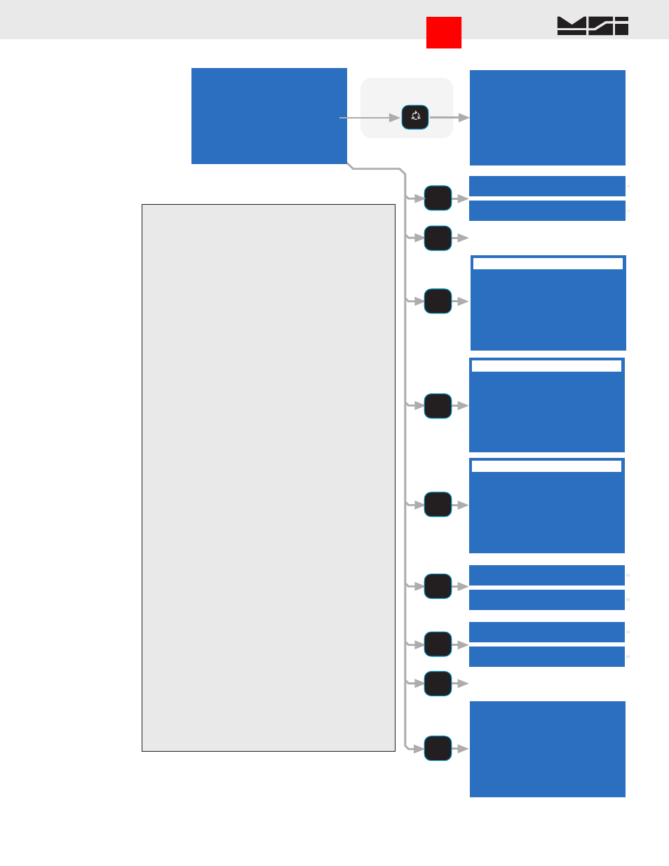
PROGRAM SET POINT MENU
1 SP
XX -SPName- OFF
2 9750 Response
OFF
3 Input Source
XX
4 Output Assign
XX
5 Delay
XXXXXms
6 Latch
OFF
7 Force On
OFF
8 Formula 9 View
1 SP
XX -SPName-
ON
1 SP
XX -SPName-
OFF
Len 0 F4 Menu
Max 8 ENT Save
Pos 1
SETPOINT XX NAME
1
VIEW FORMULA SP
XX
Set Pt Triggers If
N/G Wt >= 500.0
AND N/G Wt <=1000.0
Set Pt Resets If
N/G Wt < 500.0
OR N/G Wt > 1000.0
SET POINT DELAY ms
ESC exits no change
ENTER saves value
0-9 replaces value
1000
min = 0 max =10000
^ incs, v decs digit
OUTPUT SCAN LIST LOC
ESC exits no change
ENTER edits value
0-9 replaces value
1
min = 1 max = 32
^ incs, v decs digit
6 Latch ON
6 Latch OFF
7 Force Output ON
7 Force Output OFF
INPUT SCAN LIST LOC
ESC exits no change
ENTER edits value
0-9 replaces value
1
min = 1 max = 32
^ incs, v decs digit
To 9750 Response Menu
To Set Point Formula Menu
1
ABC
See General Text Editing
Procedure
To edit Set Point
Name
ALPHA
A
a
1
2
DEF
3
GHI
6
PQR
5
MNO
4
JKL
7
STU
8
VWX
9
@YZ
SET POINT DELAY ms
SET POINT OUTPUT LIST
INPUT SCAN LIST LOC
This Set Point Menu is reached from the procedure on
the previous page.
1) Individual Set Points are turned on (enabled) or
off (disabled) by pressing
[1]
. Disabled Set Points
can still be programmed, but will not operate until
enabled.
2) 9850 Response – This menu item sets the response
modes of the 9850. The submenus are detailed on the
next page.
3) Input Source – Input the scan channel index number
(1-32) for the scale input or math channel this set
point is compared to.
In a single Scale channel CellScale system, the input source would always
be “1” as this would be the only channel in the scan list.
4) Output Scan List Location – Input the Output List
choice for this set point. Output lists are set in the
CellScale. The output list controls the CellScale
response and has no effect on the 9850.
5) Set Point Delay ms – Set point delays are used to
eliminate spurious alarms on transient events or to
delay the set point action. Enter the desired delay in
milliseconds (1000ms = 1 second). 0 to 10000ms
range (10s). Actual resolution is 50ms. The number
will be rounded to the nearest 50ms.
6) Latch – A set point latch forces the set point output
to remain on even after the set point trip condition
is removed. Defaults to OFF.
7) Force Output – Used to test external response settings
of the set point. Forcing the output on will cause all
set point responses to operate. Be sure to force the
output back off when finished.
Caution: This function will turn on relays, warnings, alarms, etc. Be sure that
no damage will result to equipment by forcing the outputs on. This function
is automatically cleared when leaving the set point menus.
8) Formula – Use to program the set point formula. See
“Input Formula Menu”.
9) View – Shows trigger and reset points for this set
point. Used to confirm the formula. N/G indicates
the set point responds to Net or gross weight.
Go to Index