Set points, Driving output modules – Rice Lake MSI-9850 CellScale RF Digital Indicator - Operator Manual User Manual
Page 17
MSI CellScale
®
System • 9850 User Guide Page 17
MEASUREMENT SYSTEMS INTERNATIONAL
Firmware Version 5-XX for 2450 Modems
1
2
3
4
5
1
2
3
4
5
1
2
3
4
5
1
2
3
4
5
1
2
3
4
5
6
7
8
9
1
2
3
4
5
6
7
8
9
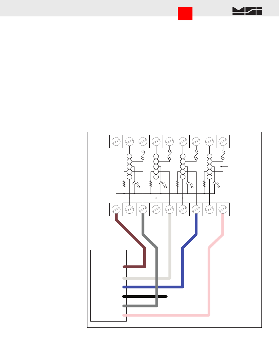
FIELD WIRING
TERMINAL STRIP
FUSE 5A
MODULE
POSITION
1
2
3
4
+VCC
GND
GND
GND
GND
LOGIC
LOGIC
LOGIC
LOGIC
TERMINAL STRIP
FOR LOGIC
9850 P3
Set Points Port
Pin 1- 5V Out
Pin 2 - SP2
Pin 3 - SP3
Pin 4 - SP5
or GND
Pin 5 - SP1
Set Points
BRN
WHT
BLUE
BLK
GREY
Driving Output Modules
Pin 5 - SP4
PINK
Use of SP5 requires
Jumper JP6
positioned 1-2.
Insulate all unused wires.
TO POSITION 5
IN LARGER RACK
GND Connections not
required for Output
modules
I/O RACK
GRAYHILL
70RCK4 or
70GRCK4 or
Equivalent
Interfacing Industry Standard I/O Modules
Standard Opto-isolated Output modules are easily driven by the 9850 Output port. MSI provides a 4 port I/O rack
prewired with the Set Points Output Cordset (MSI P/N 10082 + 13186). Hooking up the GND wire (Black) is
optional when driving output modules. Any 5V input compatible Output Module can be used. For reference, the
following Output Modules have been tested with the 9850 and fit Grayhill’s I/O Rack 70RCK4:
Grayhill AC Output Modules
70M-OAC5, 120VAC@3A, Normally-Open Zero Voltage Turn-on
70M-OAC5A, 240VAC@3A, Zero Voltage Turn-on
70M-OAC5A-11, 240VAC@3A, Random Turn-on
Grayhill DC Output Modules
70M-ODC5, 60VDC@3A, Normally-Open
70M-ODC5A, 200VDC@1A, Normally-Open
70M-ODC5B, 60VDC@3A, NO Low off leakage
This list represents only a small number of compatible Output Modules.
Go to Index