Defining the modbus register values – ADS Environmental Services FlowShark QR 775002 A4 User Manual
Page 209
Modbus
9-5
Defining the Modbus Register Values
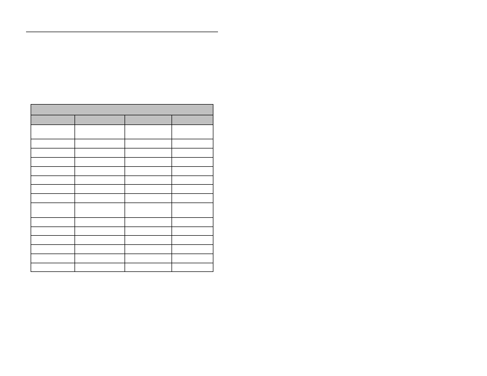
Use the information provided in the following table to select the
FlowShark output values to be received by the control system. This
table contains the most commonly configured value names and
associated register addresses.
Holding Register Definitions
Description
Profile
®
Entity
Units of Measure
Registers
Flow
FLOW1
(QCONTINUITY)
MGD
40001-40002
UniDepth
UNIDEPTH
Inches
40005-40006
Ultrasonic Depth
UDEPTH
Inches
40007-40008
Pressure Depth
PDEPTH
Inches
40053-40054
Peak Velocity
RAWVEL
FPS
40003-40004
Average Velocity
N/A (VELOCITY)
FPS
40061-40062
Rain Intensity
RAINI
Inches/Unit Time
40019-40020
Rain
RAIN
Inches
40031-40032
Number of
Samples
SAMPLES
N/A
40077-40078
Analog Input 1
Varies
Varies
40087-40088
Analog Input 2
Varies
Varies
40089-40090
Analog Output 1
Varies
Varies
40091-40092
Analog Output 2
Varies
Varies
40093-40094
Monitor Battery
BTYVOLT
Volts
40025-40026
Radio Battery
BTY_RADIO
Volts
40029-40030
Additional entities and values are available. Refer to Appendix C,
Modbus Output Registry Entities and Values, for a complete list.