5 multi-drive ladder logic program example – Rockwell Automation DeviceNet Communications Module User Manual
Page 80
8-6
DeviceNet Communications Module
Important: Comm Loss Action (A105) and Comm Loss Time
(A106) in the daisy-chained drives are not used in
Multi-Drive mode. If the RS-485 cable is disconnected
or broken, the disconnected drive(s) will fault. On the
DeviceNet side, Comm Flt Action (7) and Idle Flt Action
(8) in the MDCOMM-DNET module determine the
action taken for ALL of the drives on the Multi-Drive
node.
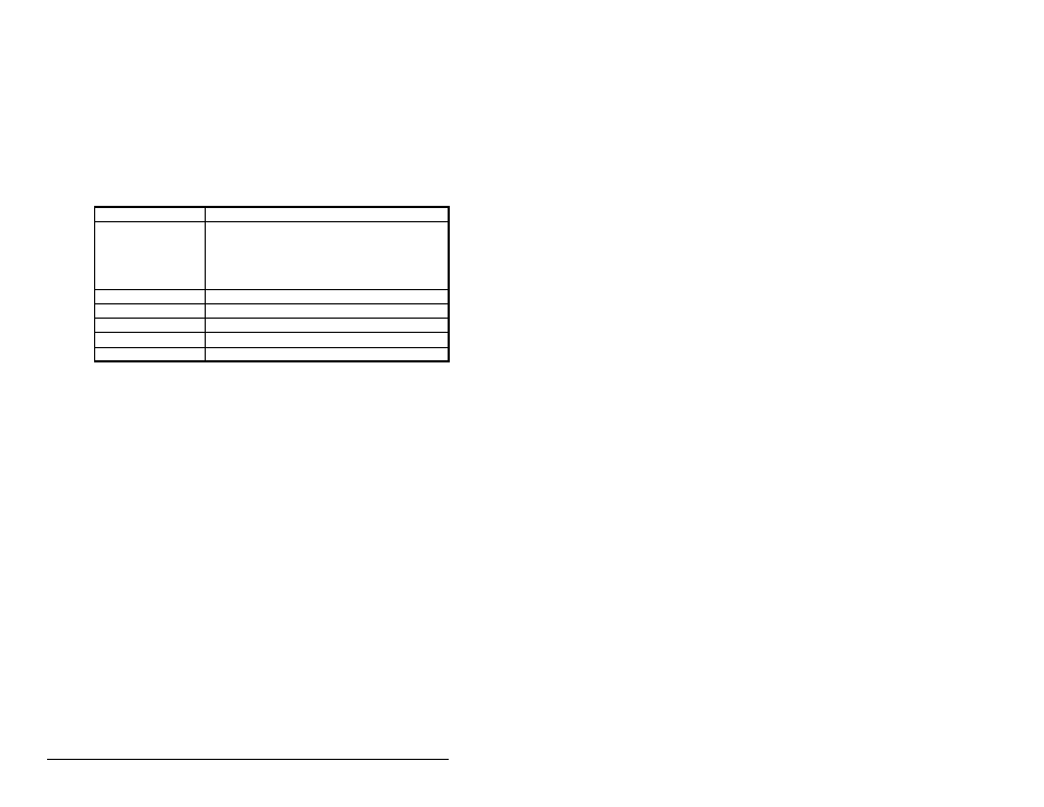
The following Multi-Drive parameters must be set in the
MDCOMM-DNET module:
After setting the MDCOMM-DNET parameters, set the module
Mode Jumper from Single-Drive operation to Multi-Drive operation,
and reset the module or cycle power. Refer to section 3.2,
Commissioning the Module.
8.5
Multi-Drive Ladder Logic Program
Example
The example ladder logic program demonstrates using Multi-Drive
mode with five drives. See figure 8.2 for a system layout diagram.
Function of the Program Example
The program example provided is for the ControlLogix, but other
controllers can also be used. The following actions can be
performed:
• View status information from the drives such as Ready, Fault, At
Speed, and Feedback.
• Control the drives using various Logic Command bits (Stop, Start,
etc.) and Reference.
• Perform a single parameter read and write for each drive. The
example uses drive parameter 39 (Accel Time) for both so you
can see (read) the change after a write is performed.
Parameter
Value
15 - (DSI I/O Cfg)
0 = Drive 0 connected
1 = Drives 0-1 connected
2 = Drives 0-2 connected
3 = Drives 0-3 connected
4 = Drives 0-4 connected
17 - (Drv 0 Addr)
= Parameter A104 - (Comm Node Address) in Drive 0
18 - (Drv 1 Addr)
= Parameter A104 - (Comm Node Address) in Drive 1
19 - (Drv 2 Addr)
= Parameter A104 - (Comm Node Address) in Drive 2
20 - (Drv 3 Addr)
= Parameter A104 - (Comm Node Address) in Drive 3
21 - (Drv 4 Addr)
= Parameter A104 - (Comm Node Address) in Drive 4