Rockwell Automation DeviceNet Communications Module User Manual
Page 44
5-4
DeviceNet Communications Module
Step 8. Select the type(s) of data exchange (Polled, Change of
State, and/or Cyclic). In our example, we selected Polled.
Step 9. Type the number of bytes that are required for your I/O in
the Input Size and Output Size boxes. The size will
depend on the I/O that you enabled in the module. This
information can be found in DSI I/O Actual (16) in the
module. Table 5.1 shows common configuration Input/
Output sizes.
In our example, we typed 4 in the Input Size and Output
Size boxes because the Mode Jumper on the module is
set to “Single” (default) and DSI I/O Active (16) is set to
“Drive 0” (only one drive being connected). Logic
Command/Reference uses 4 bytes and Logic Status/
Feedback uses 4 bytes.
Step 10. Set the scan rate. See table 5.2.
Step 11. Click OK. If you changed any settings, a Scanner Applet
asks if it is OK to unmap the I/O. Click Yes to continue.
The Edit I/O Parameters dialog box closes and then the
Scanner Module dialog box (figure 5.2) reappears. You will
map the I/O in the next section in this chapter.
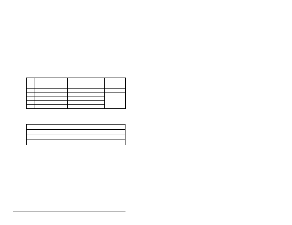
Table 5.1 – Input/Output Size Configuration
Input
Size
Output
Size
Logic
Command/
Status
Reference/
Feedback
Parameter 16 -
(DSI I/O Active)
Parameter 1 -
(Mode)
4
4
Drive 0
Single
8
8
Drives 0-1
Multi-Drive
12
12
Drives 0-2
16
16
Drives 0-3
20
20
Drives 0-4
Table 5.2 – Scan Rates
Data Exchange
Rate to set
Polled
Polled Rate
Change of State
Heartbeat Rate
Cyclic
Send Rate