Rockwell Automation 8720MC Drives Integration Manual User Manual
Page 72
Publication 8720MC-IN002A-EN-P — December 2002
3-18
Troubleshooting Your 8720MC Servo Drive
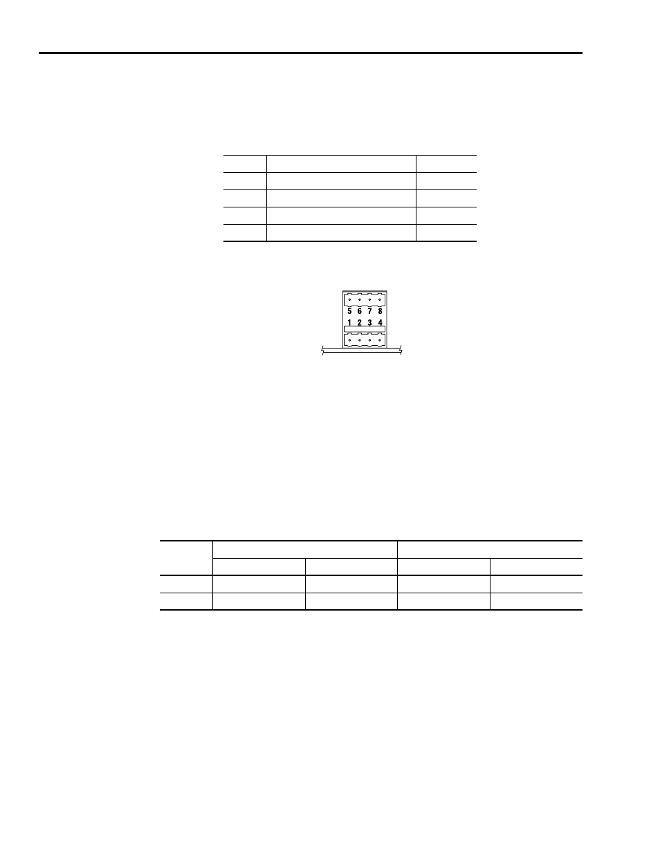
Using Analog Test Points to Monitor System Variables
There are two analog output test points accessible from the P4
connector (refer to Figure 1.1 for connector location).
Figure 3.6
Pin Orientation for P4 Connector
Refer to the 8720MC High Performance Drives Installation Manual
(publication 8720MC-IN001x-EN-P) for analog output specifications.
Refer to Appendix C for a description of the analog output parameters
(Analog Outputs 1 and 2) under parameters 681 and 683. Each analog
output has an scaling parameter associated with it (parameters 682
and 684). The analog outputs can be changed from there default
linkages in the same way as the digital outputs.
Use the two analog output test points to monitor system variables, as
shown in the table below.
The value entered in Scale Parameter will scale the analog output so
that you can get a full scale reading of the specific parameter for the
dynamic range or values you are testing.
P4 Pin
Description
Signal
P4-1
Analog Output 1
ANAOUT_CH1
P4-6
Analog Output Common
ANA_COM
P4-5
Analog Output 2
ANAOUT_CH2
P4-6
Analog Output Common
ANA_COM
P4 Connector
(8720MC Control Board)
Analog
Output
Controlling Parameter
Scale Parameter
Parameter Number
Default Value
Parameter Number
Default Value
1
0681
0040
0682
0.0060
2
0683
0084
0684
0.1000