Start-up troubleshooting procedures, Start-up troubleshooting procedures -2 – Rockwell Automation 8720MC Drives Integration Manual User Manual
Page 56
Publication 8720MC-IN002A-EN-P — December 2002
3-2
Troubleshooting Your 8720MC Servo Drive
Start-up Troubleshooting
Procedures
Before installing fuses into the AC input lines of the drive or
regenerative power supply, if supplied, first check that the incoming
AC voltage falls within the range of 324 to 505 Vrms across each of the
three phases. Make sure the AC or DC power inputs are properly
wired per the 8720MC High Performance Drive Installation Manual
(publication 8720MC-IN001x-EN-P). Also make sure the motor and
feedback devices are wired using the recommended shielded cables.
For the feedback cables make sure there is continuity between the
motor and drive connectors. Make sure the Weidmueller connector
spring clamps are clamped to the wire and not the insulation.
If you are using an 8720MC Regenerative Power Supply, refer to the
8720MC Regenerative Power Supply User Manual (publication
8720MC-RM001x-US-P) for configuration and startup information.
After power is applied to the drive the first thing to observe is the
status of the control board LEDs and the HIM display on the drive.
There are two LEDs on the control board. If you have an enclosed
8720MC Drive you must first remove the cover to observe the LEDs.
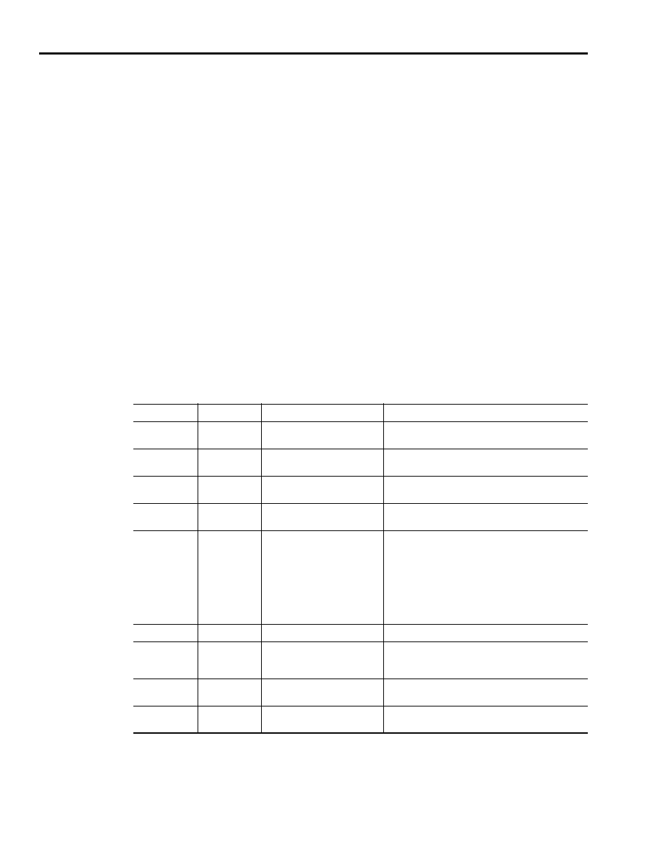
The left LED is used to indicate the status of the drive control board.
The right LED indicates the status of the SERCOS ring. The table
below indicates how these LED’s should be interpreted.
Fault messages can be displayed on the HIM, or on a PC running
DriveExplorer or RSLogix 5000 if used with SERCOS.
LED Name
LED Status
Potential Cause
Possible corrective action
Drive Status
Not Illuminated
There is no power to the Control
Board
Check the incoming AC power for AC input drives or the
incoming DC power DC for common bus drives
Drive Status
Steady Red
Malfunctioning Control Board
Software or hardware failure. Replace the Control
Board
Drive Status
Flashing Red
A fault has occurred in the
system
Verify wiring. Use the HIM fault log or DriveExplorer to
investigate the fault
Drive Status
Alternating red
and greens
DC bus is not up
Check 3 phase AC incoming or DC incoming power
Drive Status
Flashing Green
There are no faults and the DC
bus is up but the enable input is
not being detected. As a
consequence no torque is being
applied to the motor.
The drive may be in manual
mode and the jog button has not
been depressed.
• Check if +24V dc is on the enable input
• Check the run output from the RPS
• Check the enable output from the Motion Controller
• Check the enable input wiring.
• Recycle the enable
• If in manual mode depress jog button.
Drive Status
Steady Green
Drive is enabled.
No corrective action
SERCOS
Network Status
Flashing Red
There is a SERCOS ring
communication error.
Make sure the fibre optic ring is connected at all nodes
on the ring and that power is on all the nodes. Make
sure power is on the master.
SERCOS
Network Status
Steady Green
Normal operation
No corrective action
SERCOS
Network Status
Green Flashing
Establishing communications
No corrective action