Rockwell Automation 8720MC Drives Integration Manual User Manual
Page 44
Publication 8720MC-IN002A-EN-P — December 2002
2-12
Commissioning Your 8720MC Analog Drive
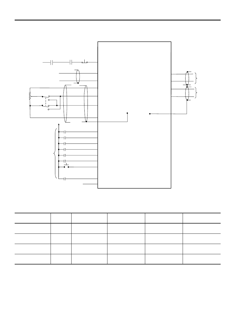
Figure 2.1
Analog Input and Output Connection Diagram
Analog default links to the 8720MC software are shown in the table
below.
Drive Error Reset
Regen PS OK
(P5-15)
(P514)
(P5-16)
(P5-17)
(P5-18)
(P5-32)
(P5-33)
(P5-34)
(P5-36)
+24 = true
P5-22 +24V dc
Jog Input
P5-22
(P5-13)
+24V dc Input Common
Jumper to P5-23
(P1-15)
(P1-14)
(P1-16)
(P1-6)
(P1-17)
(P1-5)
Analog Input 1
Analog Input 1 Return
Analog Input 2
Analog Input 2
Manual Ref
Analog Input 1
Auto Ref from Motion Controller
Analog Input 2 Return
Shields Grounded
to chassis
via Braid Clamp
Encoder Common
+9V dc encoder power
Polarity Switch
2.5 K
pot
Parameter Set Bit 2
Parameter Set Bit 1
Parameter Set Bit 0
Orient Request
Auto/Manual Select
(P4-6)
(P4-1)
(P4-5)
(P4-6)
Analog Output 1
Analog Ouput 1 Return
Analog Output 2
Analog Output 2
Analog Output 1
Analog Output 2 Return
+24V dc
Drive Enable
(Input 1)
Regen P.S.
Run
CNC
Drive
Enable
Auto Enable
8720MC
HIGH PERFORMANCE DRIVE
8720MC-B
xxx or -Dxxx
(Input 3) Drive Error Reset
(Input 5) Parameter set bit 2
(Input 7) Parameter set bit 1
(Input 9) Parameter set bit 0
(Input 2) Orient Request
(Input 4) Auto/Manual Select
(Input 6) Jog
(Input 8) Reserved
(Input 10) Regen PS OK
Connection
Parameter
Number
Analog
Spindle
Analog
Power Servo
SERCOS - Spindle /
Power Servo
SCANport - Spindle/
Power Servo
P5-14 & 15 / Analog
Input 1
661
Auto Velocity Reference
Auto Velocity Reference
Not Available
Reserved
P5-16 & 17 / Analog
Input 2
664
Manual Velocity
Reference
Manual Velocity
Reference
Not Available
Manual Velocity
Reference.
P4-1 & 6 / Analog
Output 1
681
Velocity Feedback
Velocity Feedback
Velocity Feedback
Velocity Feedback
P4-5 & 6 / Analog
Output 2
386
Motor Shaft Power
% Rated Torque
Parameter 84
Motor Shaft Power
Motor Shaft Power