Rockwell Automation 7000 PowerFlex Medium Voltage (B Frame) Commissioning - ForGe (PanelView 550) User Manual
Page 99
Rockwell Automation Publication 7000-IN006B-EN-P - May 2013
95
Commissioning the Drive Chapter 5
4. Record the value of the rectifier input voltage by looking at parameter Rec
Input Voltage (P696); for example,
V
in0
.
5. For SCR drives set parameter Idc Command Test in Current Control to
0.800 pu. For AFE drives set the parameter to 0.300 pu; for example, I
dc
.
6. Start the drive and wait for a few seconds for steady state conditions to be
established.
7. Record the value of the rectifier input voltage by looking at parameter Rec
Input Voltage (P696); for example, V
in1
.
8. Calculate the value of input impedance for AFE drives as follows:
C
in
is the value of input filter capacitor given by Line Filter Cap (P133).
9. Calculate the value of input impedance for SCR drives as follows:
10. Stop the drive. Set the Operating Mode parameter to Normal and Idc
Command Test to zero.
T DC Link (P#115) Manual Tuning
Determine an appropriate value for the T DC Link parameter from the current
regulator step response while operating in DC Current test mode. Use the
following procedure:
1. Ensure you set all parameters in the Drive Hardware and Motor Ratings
groups to the correct values. Otherwise, the calculated value of parameter
T DC Link in Current Control will be incorrect.
2. Set parameter Operating Mode in the Feature Select to DC Current to
enter the test mode.
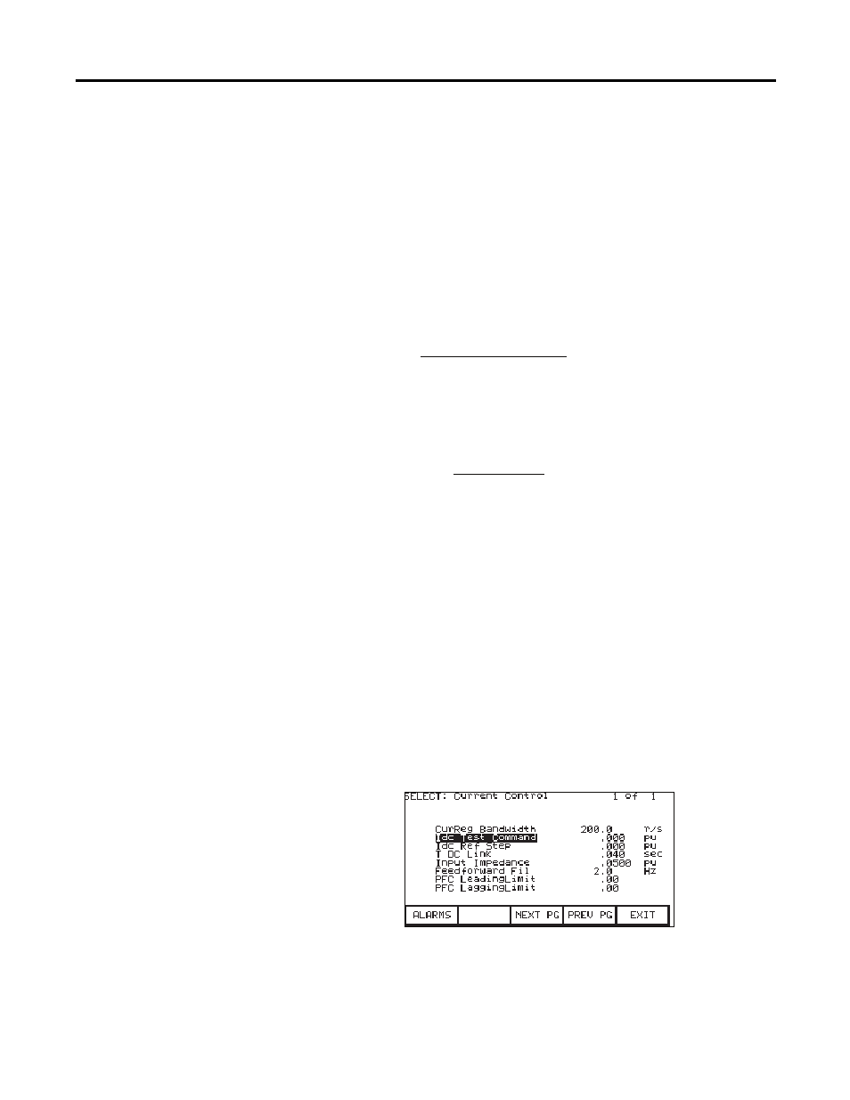
Figure 54 - Current control parameter screen
3. Set parameter Idc Test Command in Current Control to 0.225 pu for AFE
rectifier drives and 0.400pu for SCR drives.
drives
for
V
V
C
I
V
V
L
in
in
in
dc
in
in
in
PWM
)
(
1
0
1
0
⇒
−
+
−
=
drives
SCR
for
I
V
V
L
dc
in
in
in
)
(
3
1
0
⇒
−
=