Load test – Rockwell Automation 7000 PowerFlex Medium Voltage (B Frame) Commissioning - ForGe (PanelView 550) User Manual
Page 118
114
Rockwell Automation Publication 7000-IN006B-EN-P - May 2013
Chapter 5 Commissioning the Drive
Load Test
After autotuning of the drive, run the motor on load and capture the following
waveforms at 50% load and at 100% load. If the system is not ready for 100% load
test, then capture the waveforms at the max load you are allowed to run the drive
at. Also, print variables at 50% and 100% load points. Before printing variables
make sure the drive Access Level is at SERVICE.
• Capture line voltage & current waveforms at ACB test points “V2uv” &
“I2u”.
• Label the waveforms as “V2uv” and “I2u”.
• Capture motor voltage & current waveforms at ACB test points “Vuv” &
“Iu”
• Label the waveforms as “Vuv” and “Iu”.
• Save the worksheet as “Line and Load Voltage and Current Waveforms at
1048 rpm, 31 A”, for example.
Table 5 - Oscilloscope Settings
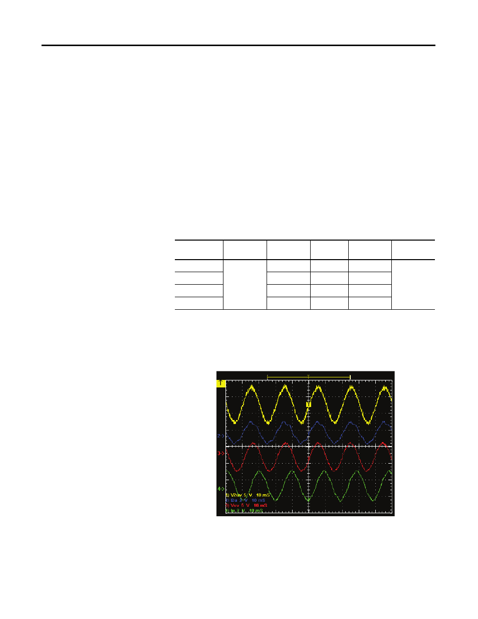
Sample Waveforms
Sample waveforms recorded on PWM drive running at full load (Ch1: Line
Voltage, Ch2 - Line Current, Ch3 - Motor Voltage, Ch4 - Motor Current)
Figure 63 - Sample waveform: PWM drive under full load condition
Oscilloscope
Time Base
Wave Form
Test-Point
Waveform
Label
Sheet Name
Chan. 1
10ms/div.
Line Voltage
V2uv
V2uv
{see above]
Chan. 2
Line Current
I2u
I2u
Chan. 3
Motor Voltage
Vuv
Vuv
Chan. 4
Motor Current
Iu
Iu