Rockwell Automation 7000 PowerFlex Medium Voltage (B Frame) Commissioning - ForGe (PanelView 550) User Manual
Page 81
Rockwell Automation Publication 7000-IN006B-EN-P - May 2013
77
Commissioning the Drive Chapter 5
Use the following procedure:
Plug the AC power connector on the test cable into an appropriate AC source.
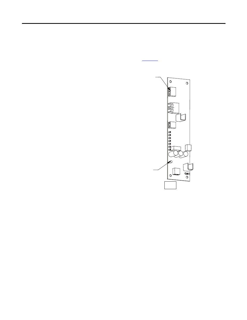
The other eighteen 3-pin connectors plug into the SCR SPGDB board terminals
labeled TB3 – Test Power (see
). The number of eighteen 3-pin
connectors used depends on the voltage and configuration of the drive rectifier
section.
Figure 48 - Self-Powered Gate Driver Board Test Power Terminal
Put the drive in Gating Test Mode and the rectifier automatically enters Test
Pattern gating mode. LED 1 – Gate Pulse (Yellow) should light up and pulsate at
the same device firing frequency. The other LEDs light up as the firmware sends a
gating signal to every SCR.
There is also a Gating Test that fires the individual devices one at a time, in what is
described as a Z-pattern. For each section, the Top Left device turns on for 2
seconds, then turns off. The next device to the right turns on for 2 seconds, and
the pattern continues.
At the end of the first stack of devices, the right device in the middle stack down
fires, and the pattern continues right to left until reaching the end of the middle
stack. Then the left device in the bottom stack fires and the pattern continues to
the last device, when it returns to the top. This tests for correct fiber optic cables
connected to the corresponding devices.
Test power connection
LED