Rockwell Automation 47C626 AutoMax Programming Executive V4.2 User Manual
Page 209
18Ć23
ON LINE Direct via Serial
C: \AMXLIB3\SYSDNYR\RACK1
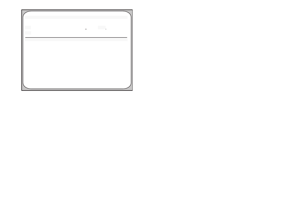
Monitor Setup UDC/PMI
EscăExit
UDC
AăPMI
BăPMI
F1 Help
Loc Port Task
VarName/RegNum
UDC ă1 S5ASPD CML_WCO%
UDC ă2 S5ASPD RES_GAN
UDC ă3
00201
UDC ă4 00690
Loc
Port Par Num
Description
Val @Ć10V Val @+10V
PMIĆA
1
ă4
ArmVolt.(Volts E0)
-32767
32700
PMIĆA
2
16
ACRMSLineV(Volts E0)
0
10
PMIĆA
3
ă3
ArmCurFdBk(Amps E1)
0
32700
PMIĆA
4
PMIĆB
1
PMIĆB
2
PMIĆB
3
PMIĆB
4
Bit
Val @Ć10V
Val@+10V
0
32767
0
255
3
-100
100
Figure 18.9 Ć UDC Setup Screen
You can display and output to the selected port any variable mapped
to a UDC register (common) or any local variable. The task name is
required for local variables.
Each UDC entry has a port number (1Ć4), a variable name or
register/bit number, and a minimum (Val @ -10V) and maximum (Val
@ +10V) value. Val @ -10V" specifies the value of the variable that
will be output as the minimum voltage, and Val @ +10V" specifies
the value of the variable that will be output as the maximum voltage.
This allows a small area of the signal range to be displayed over the
full range of the 8Ćbit digitalĆtoĆanalog converter. Values are
transferred to the analog output every scan if CCLK has been turned
on in a UDC task that is running, and every 5 milliseconds if CCLK is
off.
Each PMI entry has a port number (1Ć4), a parameter number and
description, and a minimum and maximum value. You can select the
parameter from a list of available parameters and set the Val @
-10V" and Val @ +10V" values in the same way as for a UDC
module. Only data that exists on the selected PMI Processor can be
output to one of its meter ports. Values are transferred to the analog
output after every current minor loop scan in the PMI Processor.
Use the following procedure to set up the meter ports for the UDC
modules and PMI Processors.
Step 1.
Enter S" for Set Up UDC/PMI from the Monitor menu
shown in figure 18.1.
Step 2.
Enter the slot number of the UDC module. The screen will
display the current variable name (or register and bit
number) and the minimum and maximum values for each
port on the UDC module. It will also display the parameter
number and name and the minimum and maximum values