Summary – Rockwell Automation 1785-Lx0C15 ControlNet PLC-5 Programmable Controllers User Manual User Manual
Page 67
1785-UM022C-EN-P - February 2008
Planning to Use Your ControlNet PLC-5 Processor
2-29
Summary
There are two methods to optimize the use of I/O image table in a
ControlNet PLC-5 processor. There are tradeoffs in using each
method which are summarized in the following table.
The best solution in most cases is to combine the two methods.
Examine the module requirements at any given chassis or location
and see which method fits best. You may find in some areas you have
an equal number of input and output modules, and slot
complementary optimizing works well. However, you may find in
other areas there are space limitations which require the use of the
smallest possible chassis, and therefore, you cannot waste slots using
slot complementary.
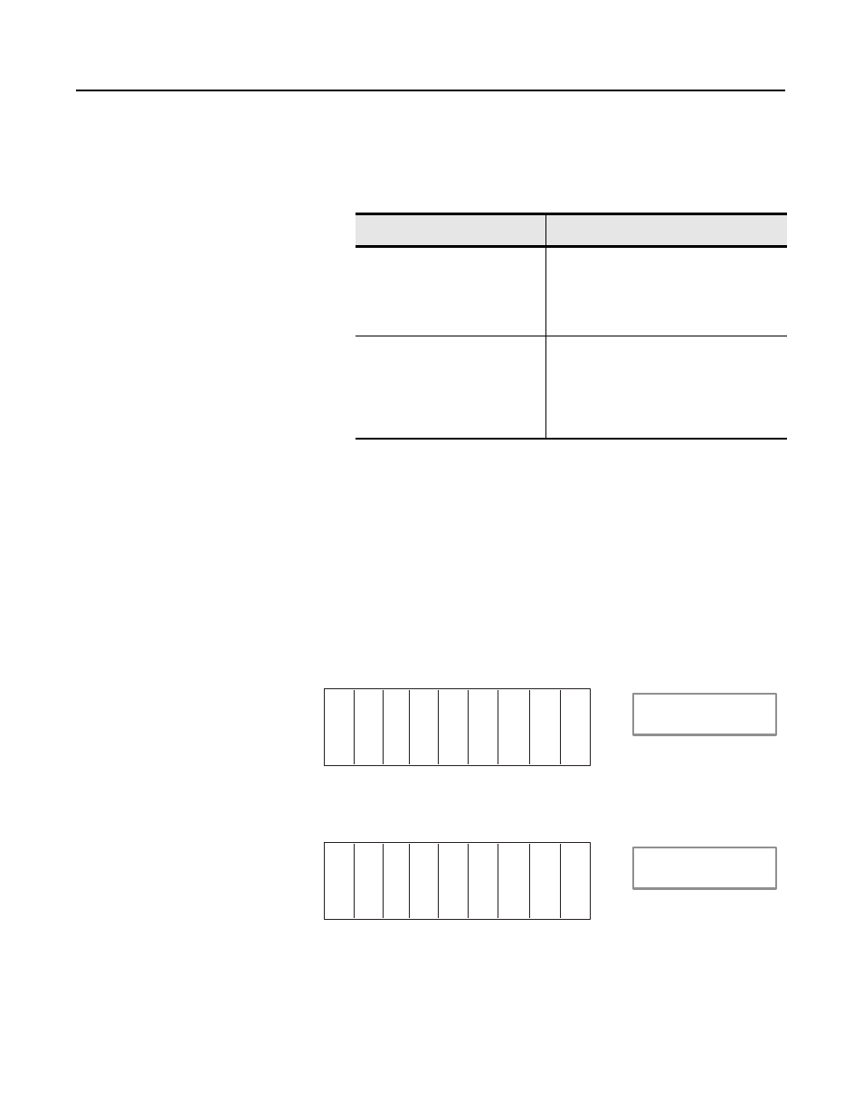
A final point to be aware of is that each system is unique and you
must apply these techniques accordingly. For example, you may have
the following chassis:
Using strict rules of optimization you might immediately arrange the
chassis like this:
Method:
Tradeoffs:
optimize without slot
complementary
• allows optimization of I/O image table, but
not to the extent if using slot complementary
• does not waste chassis slots
• can put any module anywhere (provided I/O
table exists for that slot)
optimize with slot complementary
• allows complete optimization of the I/O
image table
• can waste chassis slots and require
additional chassis
• can only put modules in odd or even slots,
depending on the module type
I
I
O
I
I
I
I = Discrete Input Module
O = Discrete Output Module
ACN = ControlNet adapter
O
I
ACN
2-slot addressing
16-point modules
O
O
I
I
I
I
I = Discrete Input Module
O = Discrete Output Module
ACN = ControlNet adapter
I
I
ACN
2-slot addressing
16-point modules