Rockwell Automation 1785-Lx0C15 ControlNet PLC-5 Programmable Controllers User Manual User Manual
Page 66
1785-UM022C-EN-P - February 2008
2-28
Planning to Use Your ControlNet PLC-5 Processor
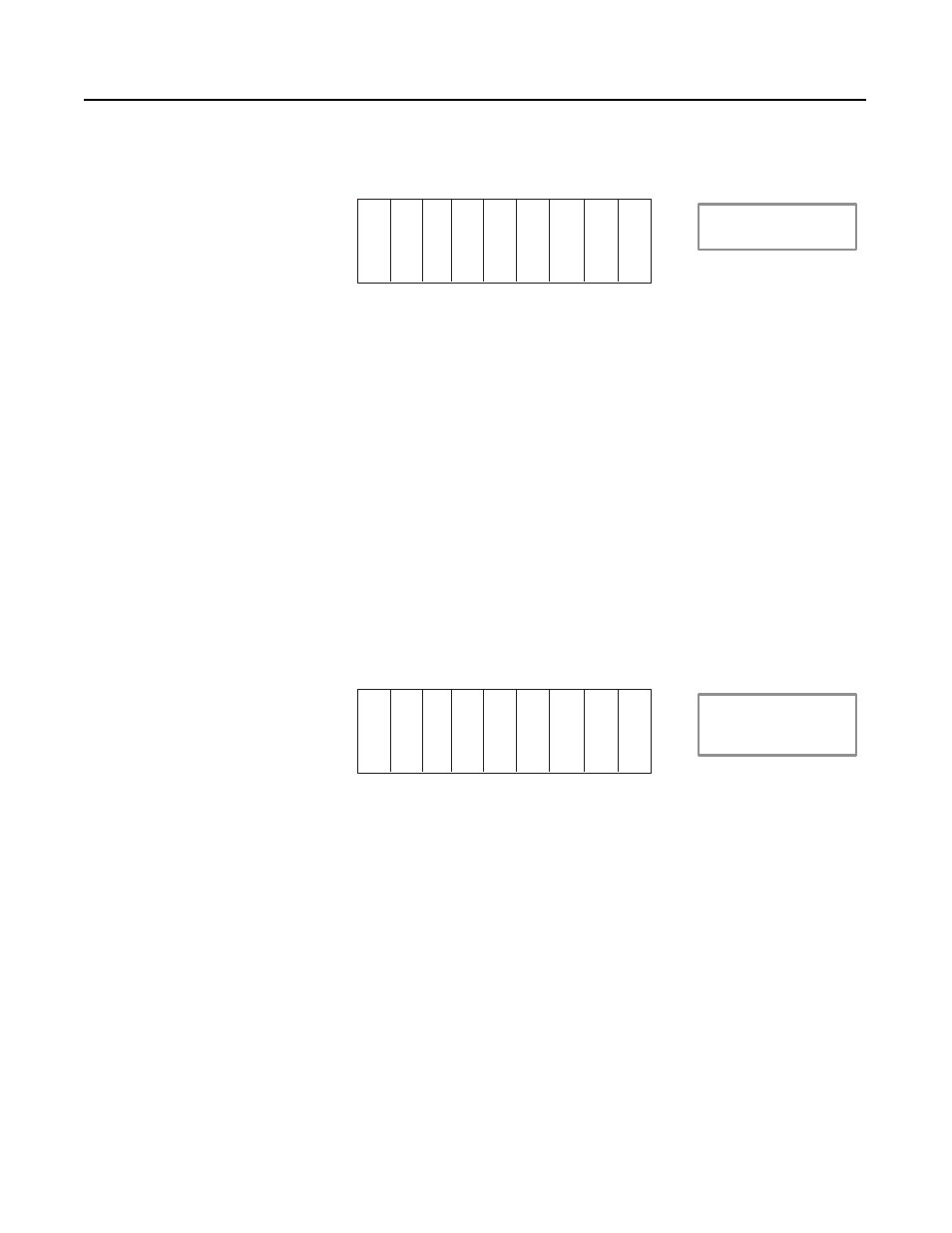
Example 1
Examine the following chassis:
In this example the first input module uses eight inputs from the first
slot and eight inputs from the second slot (not used by the output
module in the second slot). The first output module uses eight outputs
from the first slot and eight outputs from the second slot, and so on.
Given an 8-slot chassis in 2-slot addressing, there are four words of
inputs and four words of outputs used in this chassis. On a ControlNet
network, you can map four words of inputs and four words of outputs
to this chassis and no I/O image space is wasted. If you set the
addressing mode to 1-slot addressing and use the methods described
in the previous section you waste either four words of input or four
words of output image table.
This method works extremely well for cases where there are equal
numbers of input and output cards. However, in most cases there are
not the same number of each module.
Example 2
Examine the following chassis:
In this case you can map two words of input and four words of output
to the chassis and not waste any I/O image table. However, you waste
physical space (note the two empty slots).
Look at the case where you have 14 input modules and two output
modules. If you use slot complementary, you have to purchase an
additional chassis, and therefore an additional adapter and power
supply, since you can only put eight of the input modules in one
chassis (one module every other slot). If you do not use slot
complementary, you can fit all the cards in one chassis and only
sacrifice two output image table words.
With the slot-complementary method you cannot just put any module
anywhere. If you wish to add an output module to the chassis shown
above you cannot since there are no output slots available; you have
to start a new chassis.
I
O
I
O
I
O
I = Discrete Input Module
O = Discrete Output Module
ACN = ControlNet adapter
I
O
ACN
2-slot addressing
16-point modules
I
O
I
O
X
O
I = Discrete Input Module
O = Discrete Output Module
ACN = ControlNet adapter
X = Empty Slot
X
O
ACN
2-slot addressing
16-point modules