Using i/o mapping techniques – Rockwell Automation 1785-Lx0C15 ControlNet PLC-5 Programmable Controllers User Manual User Manual
Page 59
1785-UM022C-EN-P - February 2008
Planning to Use Your ControlNet PLC-5 Processor
2-21
Other ControlNet Processors
ControlNet scheduled peer-to-peer communications between
ControlNet processors require one map-table entry per message.
You can set up ControlNet peer-to-peer communications between any
two processors on a ControlNet network. The ControlNet transfer
mechanism makes it possible to map the scheduled peer-to-peer
messages listed in the following table.
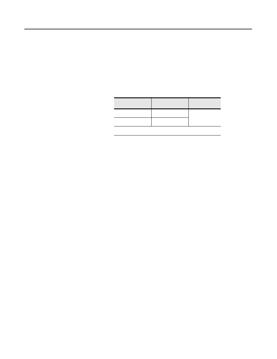
Table 2.F Peer-to-Peer Communications Mapping
To communicate between any ControlNet PLC-5 processors on the
ControlNet network, you can include MSG instructions in your
ladder-logic program. See Chapter 4 and Appendix C for more
information.
Using I/O Mapping Techniques
Discrete I/O interfaced to a PLC-5 processor is typically mapped to
the I/O image table. You can map discrete I/O to the DIF and DOF,
but you lose the ability to force the I/O if the DIF or DOF is used.
Each version of the PLC-5 processor has a specific amount of I/O
image table available, and therefore, a limit on the amount of I/O that
can be mapped to the I/O image table. Traditionally, each slot in an
I/O chassis is assigned a location in the input image table and the
output image table. While this provides very easy mapping of I/O to
the image table, it is not the most efficient way to use it. For example,
if a slot contains an input module, the corresponding location in the
output image table goes unused. With the introduction of the
ControlNet network to the PLC-5 processor family, new techniques
are available to map discrete I/O into the I/O image table in a more
efficient manner.
Input and output data can be mapped to offsets within the I/O image
tables and need not be the same size.
Message Type
Description
1
Valid Sizes
Receive Data From
Scheduled Message
1-240 words
Send Data
Scheduled Message
1
RPI Default = 4 x NUT