Rockwell Automation 1785-Lx0C15 ControlNet PLC-5 Programmable Controllers User Manual User Manual
Page 65
1785-UM022C-EN-P - February 2008
Planning to Use Your ControlNet PLC-5 Processor
2-27
Example 4
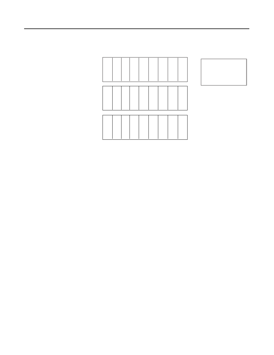
Examine the following system:
Assume you want to add an additional output module in one of the
empty slots in the second chassis. Only three words of output are
mapped to the second chassis. You have to change the output size in
the second chassis to five to get to the first empty slot. However, this
example started mapping the third chassis at O:023. If you try to set
the second chassis size to five, you get an overlap error because
words O:023 and O:024 are being used in the third chassis. You can
always change the starting address of the third chassis, but then you
must change any references to the outputs in your program. It may be
better to start mapping the third chassis at O:027 to allow for output
expansion. You can add input modules in the empty slots without
changing anything since there are already eight words of inputs
mapped to the chassis.
Optimizing the I/O Image Table with Slot Complementary
Slot complementary makes use of the ability of a chassis to share
inputs or outputs between adjacent slots. This allows you to set the
density of the chassis to a lower value than the modules used in the
chassis and then share the I/O between the slots. For example, you
can set a chassis to 2-slot addressing and then place 16-point modules
in the chassis, alternating input and output modules.
I
O
O
I
I
O
I = Discrete Input Module
O = Discrete Output Module
ACN = ControlNet adapter
A = Analog Module
PS = Power Supply
X = Empty Slot
O
O
I
A
O
A
X
X
A
I
Chassis 1
Chassis 2
Chassis 3
O
O
O
I
I
I
I
A
ACN
ACN
ACN
Input file
Input size
Output file
Output size
Chassis 1
I:010
5
O:010
8
Chassis 2
I:015
8
O:020
3
Chassis 3
I:025
7
O:023
3