Rockwell Automation 1785-Lx0C15 ControlNet PLC-5 Programmable Controllers User Manual User Manual
Page 62
1785-UM022C-EN-P - February 2008
2-24
Planning to Use Your ControlNet PLC-5 Processor
If you perform an automap on this system, the map table appears like
this:
The automap feature reserves the maximum size of inputs and
outputs. It is up to you to manually change the sizes if desired. If you
optimize the chassis as shown, the sizes adjust to the following:
There are two input modules and four output modules in the chassis.
However, you cannot set the sizes to two and four because the address
you specify is the starting address of the chassis. It identifies the
address of the leftmost slot. The size you specify determines how
many slots in the chassis written to or read from. (In 1-slot
addressing, words equals slots. The concept is the same for any
addressing mode. Words are read/written from left to write. In 1/2-
slot addressing there are two words per slot.)
In this example, the first slot in the chassis is I:010/O:010, the second
slot, I:011/O:011, and so on. The fifth slot is O:014 only. You cannot
place an input module in this slot since no input word is mapped to it.
The seventh slot has no I/O image table mapped to it. You cannot
place a discrete input or output module in the last two slots since there
is no I/O image table allocated to it.
Example 2
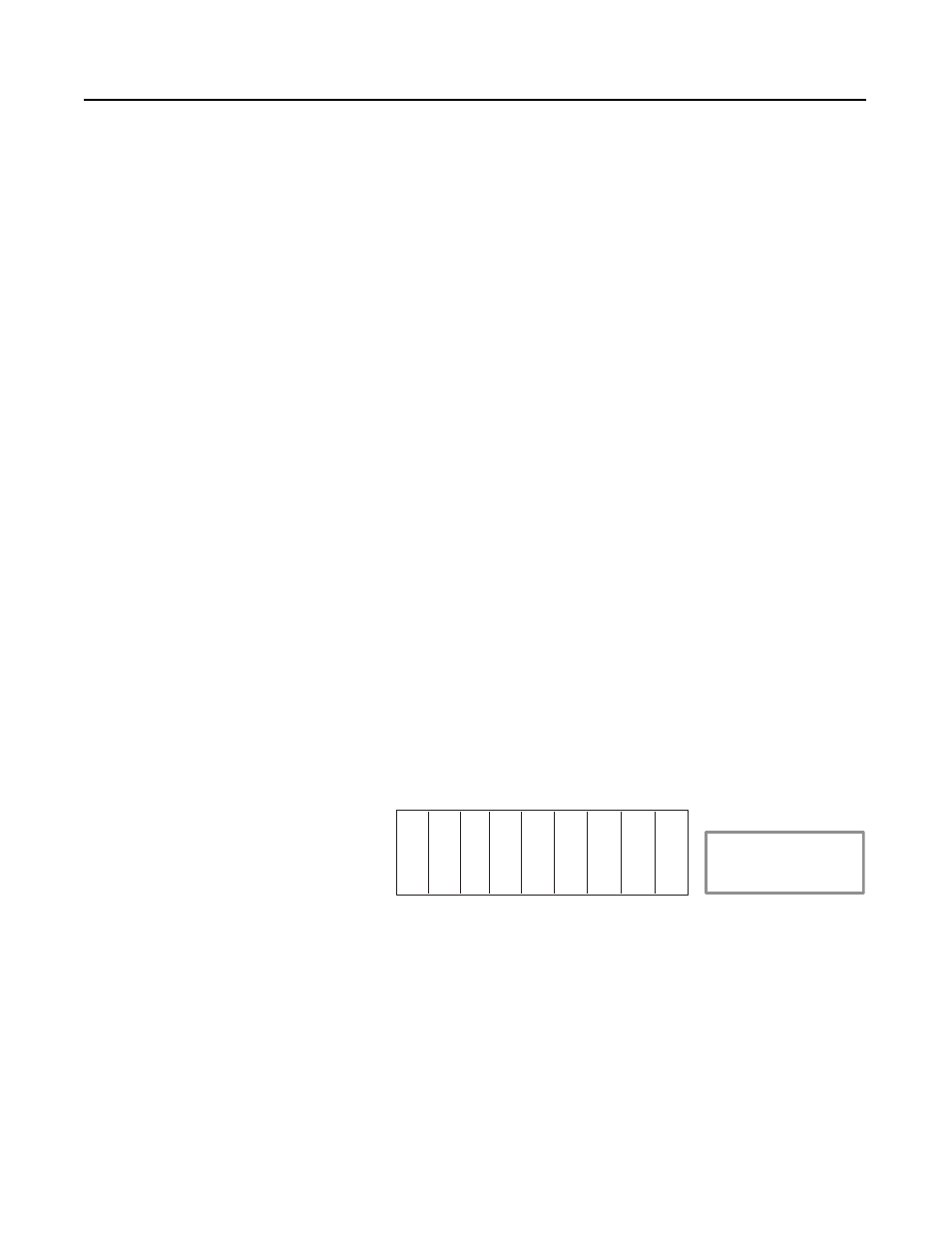
Take another look at the chassis. By moving the modules you can
optimize this chassis further. Move all the input modules to the left of
the chassis:
Now if you optimize, the map table looks like this:
By placing the input modules first, you only have to map two input
words to the chassis and do not lose any by having to pass over output
modules. The outputs only lose two words by passing over the inputs.
This example shows the first rule of module optimization.
Input file
Input size
Output file
Output size
I:010
8
O:010
8
Input file
Input size
Output file
Output size
I:010
4
O:010
6
Input file
Input size
Output file
Output size
I:010
2
O:010
6
ACN
I
I
O
O
O
O
I = Discrete Input Module
O = Discrete Output Module
ACN = ControlNet adapter
X = Empty Slot
X
X