13 appendix – JUMO 902931 Wtrans Receiver with Wireless Data Transmission Operating Manual User Manual
Page 96
13 Appendix
96
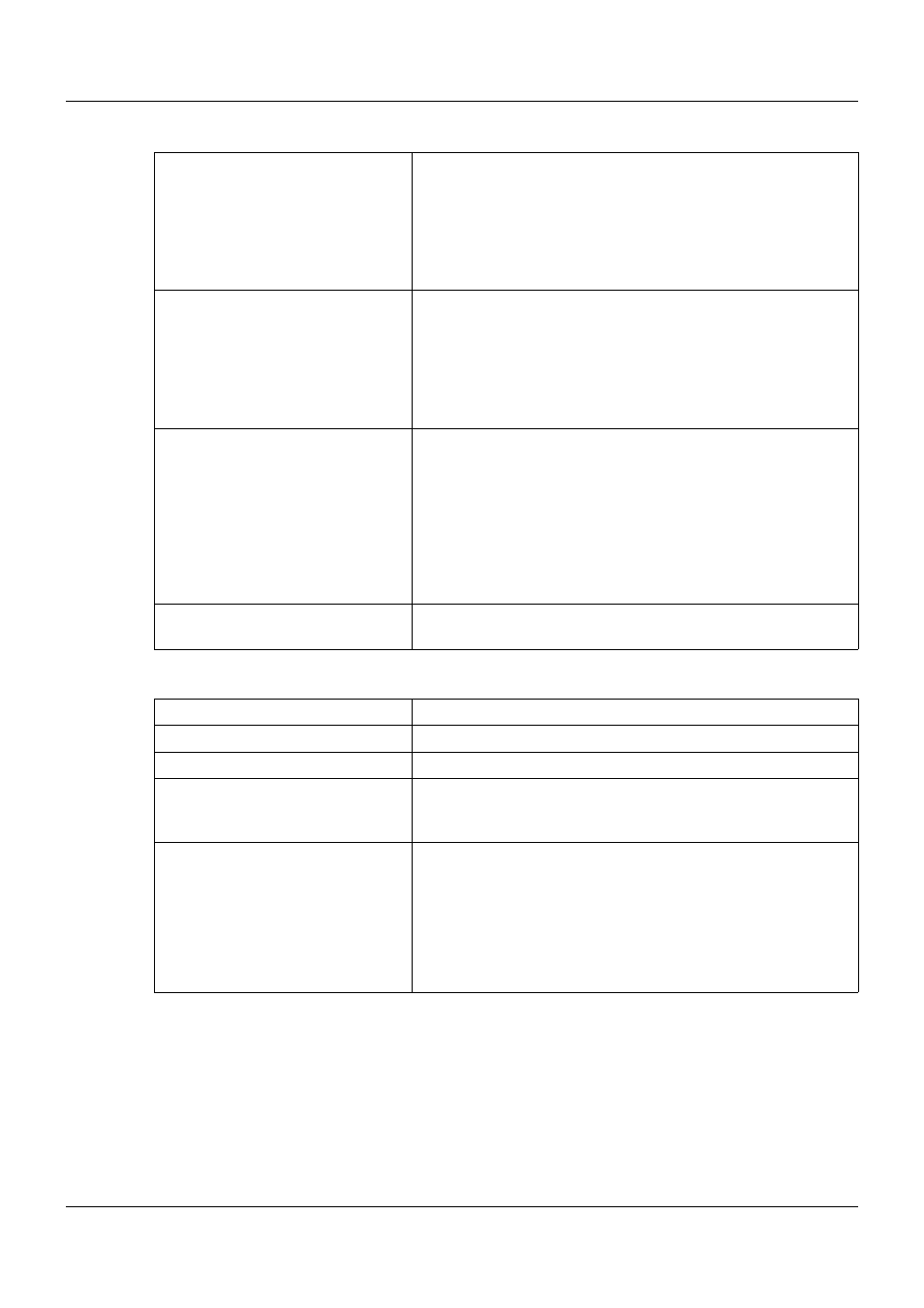
Measuring circuit monitoring of the analog outputs
Relay outputs
Underrange:
- Current output 4 to 20 mA
- Current output 0 to 20 mA
- Voltage output 0 to 10 V
Dropping to 3.8 mA,
then jump to the configured signaling
Dropping to -0.1 mA,
then jump to the configured signaling
Dropping to -0.1 V,
then jump to the configured signaling
Overrange:
- Current output 4 to 20 mA
- Current output 0 to 20 mA
- Voltage output 0 to 10 V
Rising to 20.5 mA,
then jump to the configured signaling
Rising to 20.5 mA,
then jump to the configured signaling
Rising to 10.25 V,
then jump to the configured signaling
Probe short circuit or
probe/cable break
and alarms:
- Current output 4 to 20 mA
- Current output 0 to 20 mA
- Voltage output 0 to 10 V
Positive signaling:
>
21 mA
Negative signaling:
<
3.6 mA
Positive signaling:
>
21 mA
Negative signaling:
<
-0.1 mA
Positive signaling:
>
10.5 V
Negative signaling:
<
-0.1 V
Output behavior
The output behavior (positive or negative signaling) can be con-
figured.
Number
2 relay outputs for basic type 902931/30
Relay
N/O contact configurable as N/C contact
Switching capacity
Up to 3 A at AC 230 V resistive load
Contact life
150,000 operations at 3 A / AC 230 V resistive load
350,000 operations at 1 A / AC 230 V resistive load
310,000 operations at 1 A / AC 230 V and cos phi
>
0.7
Galvanic isolation
Relay to analog outputs and interface;
Test voltage AC 3700 V (reinforced insulation)
Relay to relay;
Test voltage AC 2300 V (basic insulation)
Mixed switching of mains voltage AC 230 V and SELV or
PELV voltage is not admissible due to the basic insulation
between the relays.