1 introduction, 2 description, 3 block diagram – JUMO 902931 Wtrans Receiver with Wireless Data Transmission Operating Manual User Manual
Page 8
1 Introduction
8
1.2
Description
The Wtrans receiver T01 is used in conjunction with suitable Wtrans transmitters for mobile or
stationary measurements of physical measurands. The use of advanced wireless technology
in the industrial radio frequency 868.4 MHz or 915 MHz means that installation work is signifi-
cantly reduced and cable connections are not required. The wireless-based sensor technology
also functions in harsh industrial environments. The supplied lambda/4 antenna with an imped-
ance of 50 ohm can be screwed on directly or fitted externally. If the antenna holder for wall
mounting is used with a 3 m antenna cable, the open air range is 300 m. In the receiver, the
received measured values are converted, displayed, are available as linear current or voltage
signals (0(4) to 20 mA, 0 to 10 V), and can be accessed via an RS485 digital interface. All re-
ceiver outputs are galvanically isolated.Linkage to higher-ranking systems (e.g. the plant visu-
alization software JUMO SVS3000 or the Modbus master compatible JUMO LOGOSCREEN
nt paperless recorder) is possible via the digital interface with Modbus protocol.
Operation and configuration can be performed via the keypad in conjunction with a 2-line LCD
display, or with a setup program for greater convenience. This allows parameters such as filter
constants, offset, alarms, and drag indicators (minimum and maximum value memory) to be set
separately for each channel. For this purpose, a plug is provided on the front for a PC interface
with TTL/RS232 or USB/TTL converter for connecting the receiver and the PC.
The receiver in the mounting rail case is intended to be fitted on a DIN rail 35 mm × 7.5 mm
according to DIN EN 60715.
The screw terminals for the electrical connection are arranged in different levels. The conductor
cross section may not exceed 2.5 mm
2
.
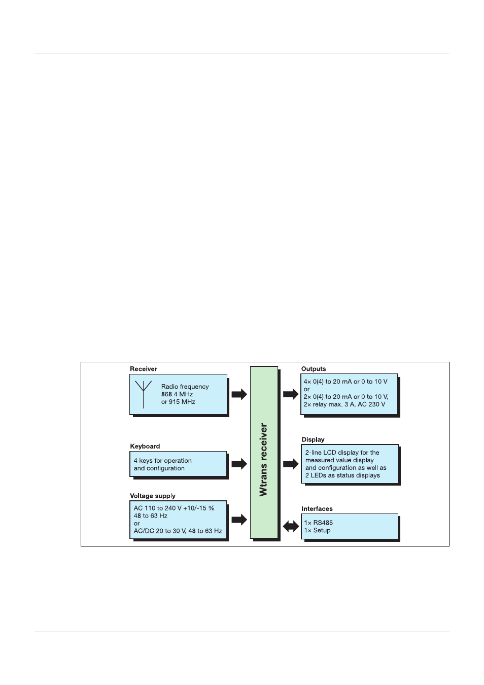
1.3
Block diagram
Figure 1:
Receiver block diagram